Hi all,
Anyone care to give me their thoughts on the compatibility of 845s in low to mid voltage push-pull using the Lundahl 1620 as the output transformer? Or compare and contrast that choice with say 2A3s or 300Bs? I am suddenly besotted by the big beasts and wonder how they would work. Or need someone to talk some sense to me.
Michael
An 8-10K Ra-a load would do the trick. How "low" of a voltage? I consider
500V low, 750V medium and anything about 1000V to be utterly out of ones
mind.
This will be a big and expensive project. It will look utterly cool and will
drive anything you could throw at it. You'd basically be reproducing a late
1940s theatre amp, or, the modulator section of a 50kW AM transmitter. Just
replace the modulation transformer with an output transformer. So, yes,
it would be fun, cool and yes you are TOTALLY OUT OF YOUR MIND!
Here's a design for PP 813 amp... You could pretty much use the same
ckt for an 845 with a few minor changes... That being the cathode bias
resistors would need to be changed to about 130V for 845s @ 1kV rather
than 81V for the 813s.
click here for schematic
You could even drop the B+ down to a nice friendly 750V. You'd want a
cathode bias of about 93V in that case... At 750V, this is what you are
facing for transformer purchases:
You need two 10V 10A transformers just to light the 845s.
Another 10V 10A transformer to light the 872B filaments - I'd use that as your
rectifier, big, pretty when running, heavy duty.
Now, you need 750V @ 400mA. The Hammonds are only good for at best
half of that... Because you really want to do choke input, you need a nice
890-0-890V with 500mA CCS rating to be on the safe side.. I'd check Peter Dahl & Company on that.... Oh.. Then the chokes... Some Big Hammonds will work there.
We're now pushing 80lbs of transformers for the PSU... Get the idea?
-- Jim
Off to the races?
Jim,
Don't you know it's not nice to encourage the insane. I have a non center tapped transformer that is built for 240V to 1750V at 750mA. Think this would work with a bridge and run from 120V? I just weighed it this morning (something I had always wondered about) and it came in at 40lbs.
I was thinking something in the 550-700V range, plate to cathode. Maybe fixed bias, maybe cathode. I have a front end designed that would feed the 845 through a Lundahl 1660PP from 12B4s. Think I could do anything in the A2 arena with that?
Michael
A project of this magnitude will require massive amounts of time.
Parts acquisition takes alot of time. Breadboarding it out could easily take a month and chew into all your weekend time. Putting it into a beautiful set of chassis that you can live with would take forever. This was my experience with a simple 450V 845 SET
that I just finished making "liveable" with. It's SET, but it is still MASSIVE. Major time suck. I'm actually going to take some time off from this hobby in the spring and come back to it late in the summer.
This is a Class A1 amp by the way... Not A2. I dont think the
1660S can do PP A2, not at least unless the grid currents are entirely balanced on both phases... A2 is an entirely different beast. You should dig up the schematic for the Altec 1570B for a study in push pull A2 ; it uses the 811A transmitting tube. Like the 845, also an eye candy tube.
This is a substantial project... Keeping it around 400-475V like I did for my SET has many advantages. One advantage is that the power supply is infinitely re-usable for manifold other projects. If you have quality high current, clean power from 400 to 475 you can power many many projects. That way, if you take an exit strategy from the 845, your time put into the PSU is not thrown away.
Power supply
Hi Jim,
Besides the transformer mentioned previously, which I think would be OK with a hybrid bridge and 866s (?), I have a 1050VCT at 400mA potted UTC that might work either as low voltage choke input or mid voltage semi cap input, ie. a 1-5uF input cap followed by the large choke. I also have a boatload of 20uF 660VAC poly/oil caps. Would need a Hammond choke or three plus the filament transformers, but they are off the shelf.
The chassis could be killer hard work though. Do you have any pics of yours?
Unfortunately for me, I am building this for a friend of mine so I would only get to live with it for a month or two while building and tuning.
Re: Class of operation. I know the 845 is designed for A1 or AB1, I was only wondering if the driver stage with the 12B4-1660S would be able to transistion to positive grid voltage for smooth overload characteristic and possibly a little of extra power. Looking at a datasheet for the 845 it doesn't seem to draw much grid current until you go more than +50V on the grid or take the plate down to <100V. If I read that right , that is. The output impedance of the 12B4-1660 may still be too high though. Just want to consider any facet of the design I can think of before solder fumes happen. Much easier to say "that won't work" now than after it's built.
Thanks,
Michael
Check this out, from Sowter, a Williamson style PP OPT with
10K plate to plate. 30 Watts. Massive. High primary L too.
Run your 845 at the 60mA/side operating point...
Sowter 8950
Another nice design of theirs is a general purpose PP 8K
tranny of EL34, 6L6 etc.
Sowter u067
Either of these OPTs leave you with an exit strategy if 845 PP
isnt your sonic cup of tea. The LL1660S is a low risk purchase
given the multiple applications available for this device.
Part of what you are chasing is the "look". You could certainly
get just a nice sound with PP 300Bs or 2A3s. You're not paying
that much extra for the "look" in this case. You already own the most expensive PSU components. You really just need one good large choke to get going. I Like the Hammond 193M 10H@300ma, 63 ohm DCR. Big. I'd use that for a nice choke input supply around 450V. At that voltage, each 845 needs 60mA around -50V grid bias. So, you're using 4*60=240mA just to bias the 845s. That leaves 60mA left for drivers... Or, a 30mA current budget per channel for all the drivers (!!) Use this sparingly!
Now, at this operating point, you need 100V between the grids at full power. This is easy. Use a low Ra, low mu tube to avoid
Miller capacitance issues with the 845... 6BX7 would be good.
So would a pair of triode strapped 6V6-GT ; both have a mu about 6. Problem is, in both cases, you'd use up all of that 30mA budget just for the driver. Thats not a problem if a 12V input sensitivity is OK with you.") Otherwise, you need one more stage of gain. Mu less than 20. 6SN7, 5687, ECC99 what not.
Otherwise, you need one more stage of gain. Mu less than 20. 6SN7, 5687, ECC99 what not.
So, you need a bigger power tranny... At least 500mA so that you
can support a 6BX7 type solution as well as another gain stage.
The 12B4 certainly has low mu and low Ra as well. It's also
a dual triode. Worth a try.
I'd go for this:
5687 -> LL1660S --> 6BX7 or 6V6 triode -> LL1660S -> 845
-- Jim
10K plate to plate. 30 Watts. Massive. High primary L too.
Run your 845 at the 60mA/side operating point...
Sowter 8950
Another nice design of theirs is a general purpose PP 8K
tranny of EL34, 6L6 etc.
Sowter u067
Either of these OPTs leave you with an exit strategy if 845 PP
isnt your sonic cup of tea. The LL1660S is a low risk purchase
given the multiple applications available for this device.
Part of what you are chasing is the "look". You could certainly
get just a nice sound with PP 300Bs or 2A3s. You're not paying
that much extra for the "look" in this case. You already own the most expensive PSU components. You really just need one good large choke to get going. I Like the Hammond 193M 10H@300ma, 63 ohm DCR. Big. I'd use that for a nice choke input supply around 450V. At that voltage, each 845 needs 60mA around -50V grid bias. So, you're using 4*60=240mA just to bias the 845s. That leaves 60mA left for drivers... Or, a 30mA current budget per channel for all the drivers (!!) Use this sparingly!
Now, at this operating point, you need 100V between the grids at full power. This is easy. Use a low Ra, low mu tube to avoid
Miller capacitance issues with the 845... 6BX7 would be good.
So would a pair of triode strapped 6V6-GT ; both have a mu about 6. Problem is, in both cases, you'd use up all of that 30mA budget just for the driver. Thats not a problem if a 12V input sensitivity is OK with you.
Otherwise, you need one more stage of gain. Mu less than 20. 6SN7, 5687, ECC99 what not.So, you need a bigger power tranny... At least 500mA so that you
can support a 6BX7 type solution as well as another gain stage.
The 12B4 certainly has low mu and low Ra as well. It's also
a dual triode. Worth a try.
I'd go for this:
5687 -> LL1660S --> 6BX7 or 6V6 triode -> LL1660S -> 845
-- Jim
Hi,
Actually the 12B4A is a single triode.
Just thought I'd set the record straight.
It's also a dual triode. Worth a try.
Actually the 12B4A is a single triode.
Just thought I'd set the record straight.
PSU
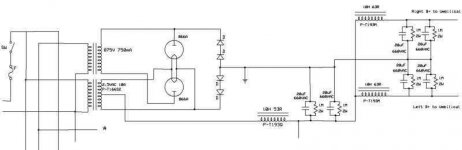
Does this seem to be drawn right? Suggestions for diodes. Yes it is missing the preamp/driver supply.
Michael
Does this seem to be drawn right? Suggestions for diodes. Yes it is missing the preamp/driver supply.
Michael
An externally hosted image should be here but it was not working when we last tested it.
Try again
Schematic
If you try this address?
http://www.msnusers.com/_Secure/0TwCz*wAX9n6MC2qydoiZ7OmrlyJVaDT2*j2UU2yGq8eCLBUUeMZ2bZRpQ7bW7o!hako1BaIu0LHfWJro*Z3ArHv4npdF1t84CmObLx7wFFqAOJevS9tkPw/PSU%20rev%201.0.jpg?dc=4675462403733935803
It appears to work sometimes, if you can get the whole address pasted into your browser. For some reason when I try to link to the image or give the url the forum editor inserts characters which screw up the address. Even when you copy it and paste it into the address bar some extra characters show up???
Could someone tell me the cure for this?
Thanks,
Michael
Hi,
I assume this is your private picture gallery on MSN?
Could it be you need to set public sharing to enable others to view it?
I'm just taking a wild guess as I noticed the word "Secure" in the URL.
Otherwise, if the pic isn't too large (600*1000 pixels max?) you can upload it here straight from your own PC.
Cheers,
Even when you copy it and paste it into the address bar some extra characters show up???
I assume this is your private picture gallery on MSN?
Could it be you need to set public sharing to enable others to view it?
I'm just taking a wild guess as I noticed the word "Secure" in the URL.
Otherwise, if the pic isn't too large (600*1000 pixels max?) you can upload it here straight from your own PC.
Cheers,
Posting pics
Hi Frank,
I have my server set to public sharing of the pictures. Did you try copying the address and going that way? It seems to not want to copy the part after the linebreak at CmO. And if I try to link directly it puts a couple extra %20 and <br> symbols that appear to be coming from the forum editor software. I know it is a long address, but.
Unfortunately if I size under the max allowable to have hosted here it is hard to make out the values in the schematic. I will try to do what I can to make it readable and post it, if nobody can tell me how to link successfully.
Thanks,
Michael
Hi,
I did and I pasted the full url but to no avail. http 405...You know that one.
Anyway, if you like you can e-mail me the pic. I'll resize it and post it for you: my moniker@hotmail dot com
Cheers,
P.S. You're not trying for the Guinness Book of Records for the longest URL ever by any chance?
Did you try copying the address and going that way?
I did and I pasted the full url but to no avail. http 405...You know that one.
Anyway, if you like you can e-mail me the pic. I'll resize it and post it for you: my moniker@hotmail dot com
Cheers,
P.S. You're not trying for the Guinness Book of Records for the longest URL ever by any chance?
more PSU questions
Hi All,
First, I have a filament transformer question. Would the Hammond 10VAC, 10A filament transformer, which I expect would be fine for AC filaments, work if I wanted regulated DC for the filaments. Not having any experience with DC regulation I don't know how much input voltage is needed to get out 10VDC.
Also, for a hybrid bridge rectifier using 2 866A, what SS diodes should I use for the other half of the bridge? A full tube bridge would be cool, but two more filament transformers and needed real estate makes that a tough way to go.
While I'm on the subject of 866s, the schematics I see with this tube show a 2.5V filament transformer for each tube with B+ taken from the center taps. The only two actual circuits I have seen using these tubes both used a 5VAC transformer with the filaments in series and B+ pulled from between the filaments. I haven't even thought about if this configuration would work with a bridge, but was wondering what the advantages and disadvantages of each setup are in a full wave circuit.
Thanks,
Michael
more questions
Hi All,
First, I feel particularly brain dead today, so could I ask if the schematic of the partial power supply is drawn in a fashion that will work properly? The wires that end in space are going to parts not included in the drawing. Sorry, I don't think the drawing is going to show, I must be banned from posting images.
Second, I was wondering about including chokes on the two legs of the secondary of the power transformer to cut RFI transmission back into the windings from the Hg rectifiers. Ditto the other side to B+. Good idea? Any suggestions for values and/or sources?
Thanks,
Michael
Attachments
Well, theoretically it looks OK. You definitely need to put a
delay on the ground lead of the graetz bridge, to permit
mercury tube preheat. Obviously we are using the hybrid
bridge to get the look of mercury, which is fine.
You could just put 3kV ceramic caps across the all rectifiers
to supress RF noise. Other than that, there are those
100uH RF chokes that are rated in the hundreds of mA range..
Z = jwL right ? I use 100pF across my merc tubes to cut
RF.
I think the right way to answer this is to get measurements..
Clearly theres an RLC equivalent here, the C from transformer
strays and the L from both the tranny and the inductance of
the 866A itself. You need to choose values that de-Q the CKT.
Here's a question. Do you need LC || LC for pushpull or will
a single LC filter do? The reason being that the PSRR of
the output stage ought to be high enough to sustain a
small amt of ripple very nicely.. You can reduce alot of weight
by eliminating a pair of 193 chokes.
It would be a very nice PSU for 750V Single Ended work thats
for sure!
Just some ideas, but what do I know, I'm a chemist not an EE.
-- Jim
Chokes
Hi Jim and All,
How would a pair of ferrite core RF chokes do on the AC side and I could wind a pair of air core for the DC side?
As for the parallel filter chokes, how much ripple can be tolerated on the B+ for the outputs in PP? It would be nice to drop them for space and expense reasons. The ripple does go up considerably, per PSUD, when they are changed to RC. I know some of the vintage stuff I work on has ripple measured in volts and is dead quiet. That all has feedback though. How much does the topology contribute to the PSRR and how much is feedback?
If I dropped the chokes then I could maybe go to my true eye candy dream. A pair of 866 and a pair of 3B28. Short of that, any suggestions for SS diode types?
I am planning a relay and a delay relay series setup for the HV. A small control transformer will make it's circuit through the umbilical and operate a double throw relay on powerup. If the umbilical is not attached the relay will remain in it's off state position which will ground the PS caps. If the umbilical is attached it will close to make 120VAC available at the delay relay which will then count down to operate to apply 120VAC to the primary of the HT transformer. seem like the right idea? I'm definitely open to suggestions here.
Jim, what sort of chemistry? I'm a ChemE, but I worked in pharmaceutical biochemistry.
Michael
Well, the feedback only operates on the input signal...
If I remember correctly, a common cathode diff pair has native
common mode noise rejection of 20dB... If you look at
Lynn Olson's work, you see that he uses a single LC stage.
There is a bypass cap between B+ at the transformer CT
and the common cathode resistor ; this provides the most serious ripple reduction in his ckt.
Aurora Rev 2
Since you have ample caps, why not forgo the extra pair of
chokes and see how it works ? You can always buy them later
and slap them into the breadboard with a few days waiting.
For an SE design, you need two LC stages in order to
decouple one B+ channel from the other to avoid internmodulation. A PP stage however, pretty much draws constant current whether idle or pushing power...
There's some other things to worry about too and thats the
choke sizing... In Morgan Jones' 2nd edition, he covers a HV
PSU design for a PP 845 amp. He poses this question:
Given a power stage at 1100V that requires 218mA, is a
10H 350mA choke sufficient ?? He shows that the total
peak current is 324mA when demanding 218mA steady state!
I dont know what you current needs are because you havent
given us an operating point yet, but that certainly would help.
At 750V, I think the 10H/300mA choke will be OK, but its best
to get the operating point data and component specs before
proceeding.
Also, you need to put in a snubber network as well, which is
missing in your schematic...
There are also other very nice mercury rectifiers out there that
have yet to be "sought after" by ebayers. The 872 tube is the
same size as the 845 tube. 10V 5A filament. Massive tube.
Easy to get. Well built. You will pay for the filament trannies though....
I'm a physical chemist BTW... Which is why I cant find any work.
I'm rather adept at building experimental apparatus. I've
also worked as a software engineer. I am one of the people that
Bush says needs to get "retrained" LOL. I suppose if you can
build photomultiplier preamps, you can learn to operate a cash register and ask "Would you like fries with that, Sir? "
-- Jim
If I remember correctly, a common cathode diff pair has native
common mode noise rejection of 20dB... If you look at
Lynn Olson's work, you see that he uses a single LC stage.
There is a bypass cap between B+ at the transformer CT
and the common cathode resistor ; this provides the most serious ripple reduction in his ckt.
Aurora Rev 2
Since you have ample caps, why not forgo the extra pair of
chokes and see how it works ? You can always buy them later
and slap them into the breadboard with a few days waiting.
For an SE design, you need two LC stages in order to
decouple one B+ channel from the other to avoid internmodulation. A PP stage however, pretty much draws constant current whether idle or pushing power...
There's some other things to worry about too and thats the
choke sizing... In Morgan Jones' 2nd edition, he covers a HV
PSU design for a PP 845 amp. He poses this question:
Given a power stage at 1100V that requires 218mA, is a
10H 350mA choke sufficient ?? He shows that the total
peak current is 324mA when demanding 218mA steady state!
I dont know what you current needs are because you havent
given us an operating point yet, but that certainly would help.
At 750V, I think the 10H/300mA choke will be OK, but its best
to get the operating point data and component specs before
proceeding.
Also, you need to put in a snubber network as well, which is
missing in your schematic...
There are also other very nice mercury rectifiers out there that
have yet to be "sought after" by ebayers. The 872 tube is the
same size as the 845 tube. 10V 5A filament. Massive tube.
Easy to get. Well built. You will pay for the filament trannies though....
I'm a physical chemist BTW... Which is why I cant find any work.
I'm rather adept at building experimental apparatus. I've
also worked as a software engineer. I am one of the people that
Bush says needs to get "retrained" LOL.
I suppose if you canbuild photomultiplier preamps, you can learn to operate a cash register and ask "Would you like fries with that, Sir? "
-- Jim
more PSU
Hi Jim,
Feedback operates on the input signal, but if there is 120Hz sine in the output it gets subtracted from the input anyway, right?
I may try the diet choke idea. The first one I have in the small scheme above is 10H at 500mA. I haven't gotten so far as picking a final operating point for a few reasons. One, not absolutely sure about going fixed bias vs cathode. Two, not sure about whether to run the LL1620 as 6k or 11.5k. Three, not sure what final output voltage of the power supply will be.
I kind of figured I would give a listen to a few different setups and see which sounded best to me. I was thinking I might start around 700V at a 100mA/tube with fixed bias and move on from there. When the tubes and filament transformers get here, I thought I would hook up to a variable supply I have that can do 200mA at 0-4000VDC, take the bias from a variable negative supply and see what it sounds like. Sound like a plan, or procrastination.
PChem, eh. It's a short haul to Analytical and then you could start designin' them there bomb sniffin machines or sumthin else that would make the Dubyah equally happy. (Please note:there is no political content in the last paragraph. It contains only career advancement advice)
Michael
- Status
- This old topic is closed. If you want to reopen this topic, contact a moderator using the "Report Post" button.
- Home
- Amplifiers
- Tubes / Valves
- 845 PP and Lundahl 1620