I have two EL 509 + an output transformer (impedance about 9.000 ohm) utilized in a 2xEL 503 push pull amplifier. I’d like to build a push pull amplifier utilizing these valves and that output transformer.
Can somebody help me? Where can I find a schematic for a push pull amplifier with EL 509 ? …or, alternatively, which values (anode voltage, current, and grid) I’d utilize to adapt EL 509 to the present circuit employing EL 503 (not available) ?
Many thanks.
Can somebody help me? Where can I find a schematic for a push pull amplifier with EL 509 ? …or, alternatively, which values (anode voltage, current, and grid) I’d utilize to adapt EL 509 to the present circuit employing EL 503 (not available) ?
Many thanks.
Thanks Frank for your replay.
Some precisations.
The amplifier I have is a push pull with 2 valves EL503.
I do not have EL 503 any more. However, now I have EL 509. So I'd build a push pull with EL 509.
My problems are:
1) Where I can find a schematic with a push-pull with EL 509 ?
...alternatively...
2) Which values of anode volatage, current and grid voltage I'd use to adapt the old amplifier to the new tubes ?
Hi,
Do you want to run it as a replacement for the EL503?
How much B+ for the output valves do you have available?
Do you want it in triode or penthode mode, Class A, AB1....?
Any reason to ditch to EL503?
I think this tube was used alot by the Italian Geloso amps...
Cheers,")
Do you want to run it as a replacement for the EL503?
How much B+ for the output valves do you have available?
Do you want it in triode or penthode mode, Class A, AB1....?
Any reason to ditch to EL503?
I think this tube was used alot by the Italian Geloso amps...
Cheers,
The amplifier is a RCF mono (for cinema).
It has been given to me without the 503s... and I have a pair of EL509 that would like to utilize in spite of the EL503s.
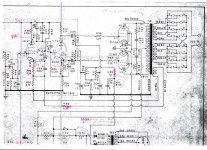
I include the schematic of the drive and power section ...so every answer to your questions are reported on it.
I'd be very grateful if you could help me.
With anticipated thanks
Antonio
P.S.
V2 and V3 = EL 503.
V1 = 6AN8
It has been given to me without the 503s... and I have a pair of EL509 that would like to utilize in spite of the EL503s.
I include the schematic of the drive and power section ...so every answer to your questions are reported on it.
I'd be very grateful if you could help me.
With anticipated thanks
Antonio
P.S.
V2 and V3 = EL 503.
V1 = 6AN8
Attachments
Hi,
If there's no specification written on the xformer, hook up a set of clip-on leads from the heater pins (4 &5 ) on the socket of the EL503 to the EL509s.
Hook up a DVM to the same pins and set it to AC in the 0 to 20 VAC range.
Switch on the amp, if after 20 seconds to voltage sags to 5.5 V or lower and the xformer gets abnormally hot, switch the amp off immediately; the xformer can't take the load.
Cheers,
Hi,
Well, I really have a hard time believing the OPT has a Zprim of 9K as stated in post #1.
For a PP of EL503s I'd expect something closer to 2K4...
Cheers,
...and, in particular, can the output transformer work correctely ?
Well, I really have a hard time believing the OPT has a Zprim of 9K as stated in post #1.
For a PP of EL503s I'd expect something closer to 2K4...
Cheers,
Hi,
Basically all you need is a VTM.
Proceed as follows:
1.) electrically remove the OT from the circuit
2.) apply a *SMALL* ac voltage to the secondary & measure it.
3.) at the same time measure the voltage from one plate lead to the other [ignoring the CT]
4.) divide these voltages to determine the turns ratio
5.) square this value & you have the impedance ratio.
Cheers,
Dear Frank,
I have performed the measurements.
Giving 0.094 V (RMS) on the secondary of the ouput trans (on the 8 ohm output), I obtained 1.56 V (RMS) at the primary.
According to your suggestions, the calculated turn ratio is 16.6.
So the primary impedance should be 16.6x16.6=275.6 -->275.6x8=2204 ohm.
At this point what do you suggest ?
Hi,
Well done...
This is what I expected. Which in your case is bad news as I can't see how we can match this to a PP EL509s.
If it's any consolation you're not the first one facing the problem of finding an alternative for the long gone EL503.
So what you're left with is either another output tube, either magnoval or octal, capable of working with the 2K5 primary in PP, another set of OPTS (not cheap) or put the project aside?
I'll try to find some time tomorrow to look what can work.
Cheers,
At this point what do you suggest ?
Well done...
This is what I expected. Which in your case is bad news as I can't see how we can match this to a PP EL509s.
If it's any consolation you're not the first one facing the problem of finding an alternative for the long gone EL503.
So what you're left with is either another output tube, either magnoval or octal, capable of working with the 2K5 primary in PP, another set of OPTS (not cheap) or put the project aside?
I'll try to find some time tomorrow to look what can work.
Cheers,

You are not the first with this problem. Here is a link for you. CHAMP ELECTRONICS
Did you ever try the EL509 s in the amp for a short time for curiosity sake ?
It is a more ruggered tube according to data.
Connecting 8 ohm speakers in the 4 ohm tap will give reflected anode impedance close to the suggested 9k.
You might like the sound.
When I measure OPT s I use 5v ac from a filament transformer instead
of 0.094v ac because my fluke digital meter cannot measure 0.094v ac accurately.
srian
Did you ever try the EL509 s in the amp for a short time for curiosity sake ?
...Connecting 8 ohm speakers in the 4 ohm tap will give reflected anode impedance close to the suggested 9k...
You're asking me?
9k anode impedance is far too high for EL509/PL519/6P45S etc.
I have built EL509 PP-amplifiers with 2k and 4 k anode loads having some 450...470 V as +Ub.
Output power is some 170 W and 100 W respectively.
- Status
- This old topic is closed. If you want to reopen this topic, contact a moderator using the "Report Post" button.
- Home
- Amplifiers
- Tubes / Valves
- schematic for a push pull EL 509