Jolida fx10 modifications.
Have already installed mur840 soft recovery diodes. Am installing upgraded grid regulators, soft recovery diodes for the microprocessor and finally reconfiguring feedback gain stage stability capacitors. Using J&J tubes.
B+ and B- are being modified as below:
Nichon Gold Tune and Solen capacitors along with ASC capacitors. Values chosen for resonance LPF cutoff frequencies into 9~10 ohms. Kiwame bleed resistors used along with metalized polystyrene clamp capacitors.
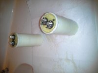
Nichon capacitors arranged in series to increase voltage rating. Solen glued together using JB weld. These are immersed in shore 40 urethane gel. Solen capacitors shielded with high platinum content gypsum gravel slurry.
ASC Capacitors to be covered in athletic tape, coated in silicone rtv, then casted into high platinum content plaster of paris to be located external to amp.
Gypsum gravel slurry, plaster of paris and tin cured urethane gel can be purchased at utrecht art supply stores.
Photos of completed work:
Have already installed mur840 soft recovery diodes. Am installing upgraded grid regulators, soft recovery diodes for the microprocessor and finally reconfiguring feedback gain stage stability capacitors. Using J&J tubes.
B+ and B- are being modified as below:
Nichon Gold Tune and Solen capacitors along with ASC capacitors. Values chosen for resonance LPF cutoff frequencies into 9~10 ohms. Kiwame bleed resistors used along with metalized polystyrene clamp capacitors.
Nichon capacitors arranged in series to increase voltage rating. Solen glued together using JB weld. These are immersed in shore 40 urethane gel. Solen capacitors shielded with high platinum content gypsum gravel slurry.
ASC Capacitors to be covered in athletic tape, coated in silicone rtv, then casted into high platinum content plaster of paris to be located external to amp.
Gypsum gravel slurry, plaster of paris and tin cured urethane gel can be purchased at utrecht art supply stores.
Photos of completed work:
Last edited:
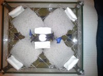
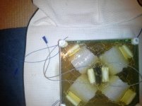
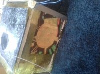
Photos included. The solen shield interiors mimic the dc metro mcphearson sq station. Inside the center is a serge lutens bell jar filled with canola oil. Notice how evenly and strongly the stopper emits the flash regardless of how it is off center. I have to further inspect the image but I dont think the flash made it to the top left corner.
Attachments
Last edited:
I dont get it, its a bunch of capacitors. Whats there to troubleshoot especially if they have been reading corect values throughout the process.
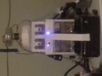
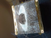
Lets highlight the benefit of adding the gel, look at the center in the last set of images. The tank was able to absorb all but the low infared where my cell phone camera is most sensitive. The ball of light is absorbed into the bell jar then released into the nichon capacitors, this ball then travels upwards to the intercrossed tines of the solens where it proceeds to roll through the tunnels back and forth in a semicircular fashion and dissipate.
If the gel and planned arangement is such a ready recpetor of of light then it should have no trouble absorbing and nullifing varations on my B+ and B- tube supplies.
The benefit of the get is that it is non conducting but increases the dielectric constant of the tank. Thus any energy not disipated by the capacitor groupings should be released at significantly higher wavelength before it exits the chamber. This limits the noise released back into the system in impulse and feedback fashion. As well keeping continous noise out of the system will reduce the impact of frequency locked capacitor degredation. This is where a capacitor forms a ripple in its surface and is unable to further filter that/those frequencies.
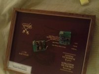
Hmm, im pretty sure that the legs of the solens were straight at some point. I believe that the lower left of the unrotated image is nearest to the bathtub drain. This is the corner where the power cord will enter.
Upon double checking, I believe it to be caused by light defraction causing the camera to mislocate the leg curvature when impacted by the flash. The legs are rotated to my eyes but seem to be paralell in each solen grouping. Then again the glue is still wet.
Regardless due to the nature of the urethane gel, the process of applying energy should impact the chain linking and bonding thus liquifing it again to be linked by the tin again.
Hopefully it remains a solid when the tape is removed. The original lid for the jolida fx10 has vent slots located along the outer edges which now form the bottom of the chamber.
The ASC capacitors are quite intense as well. When speaking towards the top while holding them in my hands, my ability to speak slowly dissapears.
I believe this is due to them depolarizing the nerves in my vocal tract.
Surprisingly they dont even have bleeder resistors and small clamp capacitors instaled yet.
I believe this is due to them depolarizing the nerves in my vocal tract.
Surprisingly they dont even have bleeder resistors and small clamp capacitors instaled yet.
ASC caps do that. That's how you tell they're genuine and still working. Since you're already holding the cellphone camera (best tweaking tool, better than scopes), take some time to take more pictures on just one of the pins. Either pin will do. This will help to improve polarity and allow the dielectric to absorb some IR without being nullified. You will hear less hum and more sound stage as the actual intrinsic capacitance value increases as it becomes more and more polarized.
Sent from my ASUS_T00G using Tapatalk
Sent from my ASUS_T00G using Tapatalk
I feel something pulling on my leg.
Probably going for the Pul-itzer

Mona
Jolida fx10 modifications.
Have already installed mur840 soft recovery diodes. Am installing upgraded grid regulators, soft recovery diodes for the microprocessor and finally reconfiguring feedback gain stage stability capacitors. Using J&J tubes.
B+ and B- are being modified as below:
Nichon Gold Tune and Solen capacitors along with ASC capacitors. Values chosen for resonance LPF cutoff frequencies into 9~10 ohms. Kiwame bleed resistors used along with metalized polystyrene clamp capacitors.
Nichon capacitors arranged in series to increase voltage rating. Solen glued together using JB weld. These are immersed in shore 40 urethane gel. Solen capacitors shielded with high platinum content gypsum gravel slurry.
ASC Capacitors to be covered in athletic tape, coated in silicone rtv, then casted into high platinum content plaster of paris to be located external to amp.
Gypsum gravel slurry, plaster of paris and tin cured urethane gel can be purchased at utrecht art supply stores.
Photos of completed work:
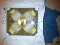
Photos included. The solen shield interiors mimic the dc metro mcphearson sq station. Inside the center is a serge lutens bell jar filled with canola oil. Notice how evenly and strongly the stopper emits the flash regardless of how it is off center. I have to further inspect the image but I dont think the flash made it to the top left corner.
Photos. Filled the tank, added more wires, gelled the ASC capacitors.
I dont get it, its a bunch of capacitors. Whats there to troubleshoot especially if they have been reading corect values throughout the process.
Lets highlight the benefit of adding the gel, look at the center in the last set of images. The tank was able to absorb all but the low infared where my cell phone camera is most sensitive. The ball of light is absorbed into the bell jar then released into the nichon capacitors, this ball then travels upwards to the intercrossed tines of the solens where it proceeds to roll through the tunnels back and forth in a semicircular fashion and dissipate.
If the gel and planned arangement is such a ready recpetor of of light then it should have no trouble absorbing and nullifing varations on my B+ and B- tube supplies.
The benefit of the get is that it is non conducting but increases the dielectric constant of the tank. Thus any energy not disipated by the capacitor groupings should be released at significantly higher wavelength before it exits the chamber. This limits the noise released back into the system in impulse and feedback fashion. As well keeping continous noise out of the system will reduce the impact of frequency locked capacitor degredation. This is where a capacitor forms a ripple in its surface and is unable to further filter that/those frequencies.
Hmm, im pretty sure that the legs of the solens were straight at some point. I believe that the lower left of the unrotated image is nearest to the bathtub drain. This is the corner where the power cord will enter.
Upon double checking, I believe it to be caused by light defraction causing the camera to mislocate the leg curvature when impacted by the flash. The legs are rotated to my eyes but seem to be paralell in each solen grouping. Then again the glue is still wet.
Regardless due to the nature of the urethane gel, the process of applying energy should impact the chain linking and bonding thus liquifing it again to be linked by the tin again.
Hopefully it remains a solid when the tape is removed. The original lid for the jolida fx10 has vent slots located along the outer edges which now form the bottom of the chamber.
The ASC capacitors are quite intense as well. When speaking towards the top while holding them in my hands, my ability to speak slowly dissapears.
I believe this is due to them depolarizing the nerves in my vocal tract.
Surprisingly they dont even have bleeder resistors and small clamp capacitors instaled yet.
In the end dude, I do get that car out front...I hope you know that renn. I hope that pisses you off more than bathrooming on my thread...?

One thing to take note of with urethane gel. The set time can be quite lengthy, especially if it is a large quantity. It may help to take the device out into the hot sun. Personally, I use a large drying cabinet with shelves built into my clothes dryer.
And dont worry about the bubbles. Thats how you know its working. In fact they will enhance internal reflection of outputted old noise while helping to maintain a clean magnetic field trapped within the gel for power reserves.
Quite nifty...I guess capacitors(radiating devices) create their own bubbles of varying density in an air media as well. Cool!
On another note, this slightly relates to the importance of bleeder resistors in a analogy sort of way. Just be sure that it wont impact feedback frequency cutoff calculations in a resistor divison calculation..
Last edited:
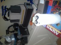
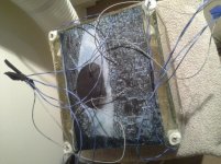
Well, the 2.136 mF of the tank blew out the primarys on the input transformer while trying to charge it to 330 V. I have acquired a suitable toroidal plitron to replace the current EL core. The output impedance matching(think voltage division) and buffer transformers will be changed from their current EL core to a suitable toroidal plitron of smallest size available for increased speed.
The gel currently has added roughly 158 uF of quickly attainable capacitance as well as considerably more less quickly attainable capacitance. My basic handheld lcr meter is unable to measure this latter figure.
As everything is now out of the case, the grid bias voltage will be rectified and flattened with capacitors. The debounce capacitors on the channel switches will be upgraded as well as the input dc filters and high frequency feedback filter capacitors.
The push button power and power switch will be removed to simply use the power plug to control on/off state.
Photos of the tank attached.
Attachments
Last edited:
Here are photos of the correction:mur860 rectifier diodes scavanged from a seriously fried dynahi power supply board. The 0.1 uF ceramic capacitors will be replaced with 47pF radial polystyrene capacitors and bled with kiwame resistors 100Kohm per diode.
Photos attached
Photos attached
Attachments
Last edited:
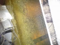
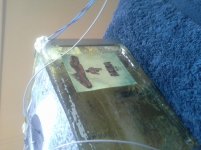
Here is a more recent photo highlighting the power transfer to/from the power socket highlighted by the darker stain caused by the fluid moving to the ac recepticle. This is another possibility for the shorted transformer by forcing the transformer to dissapate the excess noise that was not filtered by the tank.
This noise forced itself into a feedback loop thus amplifying before it was able to burn a hole in the filtering capabilities of the tank/reach a stable state in the tank. The switch to soft recovery diodes should help this as well as the removal of a post rectification piece of TI Shield located near the IEC which caused the power supply to attract significant RF without readily dropping it back to the power line. Rather it was more attracted to the tank...
I believe the use of TI Shield would be better served farther from the tank pre rectification or used in a more cautious manner...this stuff has killed many a power supply
Attachments
Last edited:
- Status
- Not open for further replies.
- Home
- Amplifiers
- Tubes / Valves
- Jolida FX10 mods