Here's a link to the description.
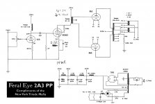
And here's the schematic.
So I looked up the specs of the discontinued Tango iron and found this:
Looks to me like the following Lundahl would be a close match:
And here's the schematic.
So I looked up the specs of the discontinued Tango iron and found this:
- TC-160 choke: 160H @ 15mA or 40H @30 mA
- NC-14 interstage: 1+1:1+1, 50H primary, 160Vrma max output, 30mA DC current max
- XE-45-5 output: 5k primary, 45W, multiple secondary taps, some kind of FB winding?
Looks to me like the following Lundahl would be a close match:
- choke load, LL 1668, $100
- interstage, LL 1660, $115
- output LL 1620CFB has the feedback taps, 6k primary, $260
In general, be careful about the amount of cathode feedback as the driver might run short of swing. The Lundahl has rather high amount at 25%.
I don't know the Tango XE-45-5.
However I can't see the point of using the 2A3 with cathode feedback. Very low distortion can be obtained without. Damping factor would not change much because the open loop gain is low and you still have the full Rdc of the transformer in series. The added complexity is not worth for me.
Besides if you use for example the Lundahl LL1623 @ 0.2 dB power loss instead of the LL1620 @0.5 dB power loss the Rdc of the LL1623 is much lower!
Apart from the cathode feedback issue the transformers you want to use are ok.
I personally don't like LC coupling.
The Hashimoto A105 is identical to the Tango NC-14 in everything except the DC current it can work at. This is precisely 1/2. This also results in a lower max rms voltage output (at low frequency) because at any equivalent configuration the inductance is the same but max DC current is 1/2.
45, what is it about LC coupling that you don't like?
Because you add a resonance.
CCS and R load, C coupling and DC coupling in any mix or proper interstage transformer all work better for me in that position.
In this case 160H + 0.1 uF means 40Hz resonance. Despite the fact the peak might be damped by the large grid resistor the phase won't change.
However I can't see the point of using the 2A3 with cathode feedback. V
In that case, the LL 1663 @ $145 might be another potential OPT?
I wonder if a resonance at 40Hz was part of what the author liked about the original design. If using full range speakers in modest cabinets, that might make sense.
This is coming from the choke load and coupling cap, correct? I was looking at the interstage at first and trying to figure out what you meant.
LL1663 is good and actually more in line with the power rating of your amp. It is rated 40W @30Hz, so it's still 18W @20Hz. A bit less if some small unbalance is present. Power loss 0.3 dB still better than 1620 used @0.5 dB power loss.
I cannot say about the author's choice. I have seen this other times and those times where it wasn't properly calculated I asked and realized people were not aware it is a resonant network.
The transformer has no resonance at low frequency and if properly made will have his first resonance well above 20KHz.
I used LC coupling once for a 300B driver with the 46 triode in the prototype stage while waiting for the IT transformers. It was something like 40H + 4.7uF high quality film cap and 15K next stage grid resistor and it didn't sound bad. However once replaced with the Tango NC-20 interstage the difference was almost like night and day.
Last edited:
I have built Feral Eye amplifier as per original schematic, however I faced some issue with the 6V6G tube which I have bought from this auction
6V6G CV509 FIVRE NOS BOXED VALVE/TUBE | eBay
When I first turned on the amplifier I didnt heard any sound. After measurements I have found that there is ~250VDC on pin5 of 6v6g. I thought that maybe coupling cap has leakage but its not the case. I have also lowered grid resistor from 820k to 300k, however it also did not helped.
To make long story short - I cannot figure out why there is no minus voltage on 6v6 grid - any ideas?
In the meantime I made EL84 to 6v6 adapter and with EL84 it works good, no issues at all, same circuit.
Can it be the case that there is some internal short in 6v6g? I have two pcs, both bought as NOS with the same issue.
What are the voltages on each of the pins of the 6V6?
What’s the voltage from the cathode to ground?
Also, I breadboarded this amp several years ago. It sounded great. I tried with and without the cathode feedback. It measured better with the feedback but it really sounded the same with or without it.
What’s the voltage from the cathode to ground?
Also, I breadboarded this amp several years ago. It sounded great. I tried with and without the cathode feedback. It measured better with the feedback but it really sounded the same with or without it.
The original schematic shows that there is a self bias resistor and bypass cap on the 6F6 Cathode. It should be a few volts positive.
The control grid, pin 5 is not supposed to have any DC bias voltage on it at all.
If the EL84 works in that circuit, I would check the 6V6 tubes on a tube checker.
Could they be a Bogus 6V6? (a different pin out, but stamped with 6V6 markings).
The control grid, pin 5 is not supposed to have any DC bias voltage on it at all.
If the EL84 works in that circuit, I would check the 6V6 tubes on a tube checker.
Could they be a Bogus 6V6? (a different pin out, but stamped with 6V6 markings).
I kept 750r bypassed 100uf/50v on 2nd tube cathode.
How NC14 should be wired in this circuit?
I have tied pin 9 and 10 together, pin11 - plate, pin8 - B+
Pin 4+5 tied together and to GND, pin3 to first 2a3 grid, pin 6 to second 2a3 grid.
i believe this is a series connection while it should be parallel to handle 30mA, am I right?
Parallel:
8 tied with 9, 10 tied with 11. 8 B+, 10 to plate. No changes on secondary.
Do you think this might be the issue?
O, the problem is solved. There is some issue with those 6v6 tubes I have bought, with russian 6v6 it works good.
Nevertheless Feral Eye schematic is not precise. 750r cathode resistor with 31v across on it is equal to 41mA current which is too much for NC14 serial wired.
Secondly on schematic you can see BG 50uf/16v cap across 750r resistor. How it can be 16v if on the same schematic we see 31v across the cathode resistor.
Doesnt make sense.
Indeed there seems to be an error in the schematic.
Checking 6F6GT datasheet, with some 280V plate voltage, 31V grid voltage and 750 ohm cathode resistor, there should be no more than 12-15 mA plate current.
")
Using a cathode bypass cap that is only rated for 16V for a cathode that is 31V above ground will cause lots of DC current in the cap (excess leakage current). Then if the cap heats up enough, it may explode.
The new current will depend on whether the exploded cap is now open, or is now shorted.
The new current will depend on whether the exploded cap is now open, or is now shorted.
Mr Reichert wrote the following:
"To hook them up correctly it is important to measure the gain of the amplifier with the heater trans CTs connected to alternate sides of this coil. The connection with the lowest gain is the correct wiring and the one with the higher gain is the positive feedback version."
Does it makes a difference if 1st or 2nd HT CT will be connected to CF1 or CF2 tap on the output trance?
My understanding is the following:
IF Output tube no1 is connected to P1 (plate 1), then HT CT of that tube should be connected to CF1 tap.
Same with 2nd tube, P2 tap, CF2 tap.
All taps on Tango are marked, for a reason, am I right or wrong?
OK, I've tried both options of connecting heater CT to different sides of cathode feedback coil.
option 1 - less gain, very good clarity and details, lifeless presentation with no "body" in sound.
option 2 - more gain, less clarity, more colorful and full bodied presentation with slam and drive. Slightly blurred vs option no1.
What is the technical difference between these two options? "Positive feedback" version mix the signal of both tubes together?
- Status
- This old topic is closed. If you want to reopen this topic, contact a moderator using the "Report Post" button.
- Home
- Amplifiers
- Tubes / Valves
- Anyone ever tried building the Feral Eye 2A3 PP?