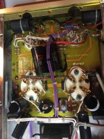
I acquired 2 Dared DV-300b monoblocks. They are in working order, but inside 4 resistors (2 in each monoblock) have broken their casing.
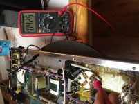
I can't read their value, since their casing is gone. I have tested them with a multimeter, in circuit, and they both measure 83K ohm.
Would be safe to assume these are 83K? How about the watts?
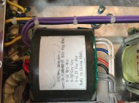
On the transformer a sticker says output is 300-315v. I'm not expert and using this online calculator (Voltage current resistance and electric power general basic electrical formulas mathematical calculations calculator formula for power calculating energy work equation power law watts understandimg general electrical pie chart electricity calculation) inputting only 83k ohm and 300v I get out 1watt.
These resistors though seem very big. What wattage should I replace them with?
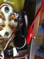
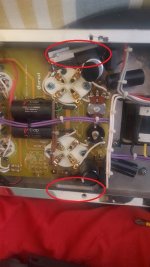
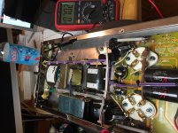
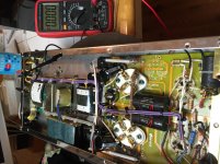
As you can see from the photo, the PCB around the resistors is burned and the nearby capacitors did melt their plastic wrap.
The person I got the amps from said the PCB were burned already years ago, but surely the burned got a bit darker year after year of use. It seems that the PCB already went through some repair, as there look to be some sort of patch under one of the resistor.
These particular units have been modified by Response Audio. I have tried to contact them, but so far had no reply. Dared has not been able to provide me schematics either, so I'm not sure if these resistors were part of the modification Response Audio did.
Thanks in advance for all the help!
I can't read their value, since their casing is gone. I have tested them with a multimeter, in circuit, and they both measure 83K ohm.
Would be safe to assume these are 83K? How about the watts?
On the transformer a sticker says output is 300-315v. I'm not expert and using this online calculator (Voltage current resistance and electric power general basic electrical formulas mathematical calculations calculator formula for power calculating energy work equation power law watts understandimg general electrical pie chart electricity calculation) inputting only 83k ohm and 300v I get out 1watt.
These resistors though seem very big. What wattage should I replace them with?
As you can see from the photo, the PCB around the resistors is burned and the nearby capacitors did melt their plastic wrap.
The person I got the amps from said the PCB were burned already years ago, but surely the burned got a bit darker year after year of use. It seems that the PCB already went through some repair, as there look to be some sort of patch under one of the resistor.
These particular units have been modified by Response Audio. I have tried to contact them, but so far had no reply. Dared has not been able to provide me schematics either, so I'm not sure if these resistors were part of the modification Response Audio did.
Thanks in advance for all the help!
Attachments

Without knowing about their position in the circuit we can't say for sure that measuring them in-circuit is reliable.
The fact that they both read the same and the amps still work suggests that reading them out-of-circuit would probably give a good reading. Hopefully their resistance isn't changed much due to losing their coating.
as for the wattage, measure the voltage drop across the resistor in use, calculate ohms law, and give yourself some headroom - 30-50% - when selecting the replacement resistor.
That sure looks like a wirewound type resistor to me, so it should be safe to replace it with another wirewound resistor. Potentially the kind that is already potted in a heatsink. which you can bolt to the chassis.
How do I measure the voltage drop across the resistor?
Voltage drop measurement is the same as resistance measurement, setting your DVM to voltmeter.
")
I'm not sure at all these resistors even has "coat". These are typical old style (I have similar resistors made at sixties) nude wirewound resistors between 8-20W.
The original resistors (R20 marking?) carbonized PCB, probably these has long legs and placed far from other components.
From everything I've seen of Dared amps, they're not original resistors. Dared amps use green 15 watt bias resistors that I believe are 800 ohms.
Also, the photos clearly show that a different level of skill was available doing the solder joints. The original joints are clean and look well done where as the burned resistors and a few other areas show leftover flux and poor soldering skills.
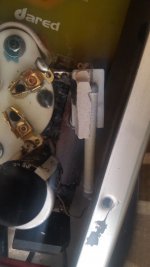
If you look at the pots, the black one is typical of Dared amps but the plain metal one is different from other Dared products.
Maybe your amp has been F.....d with!
Also, the photos clearly show that a different level of skill was available doing the solder joints. The original joints are clean and look well done where as the burned resistors and a few other areas show leftover flux and poor soldering skills.
If you look at the pots, the black one is typical of Dared amps but the plain metal one is different from other Dared products.
Maybe your amp has been F.....d with!
Yeah, the soldering is not looking very clean
I would be curious to see how a stock Dared DV-300B looks like to spot which modifications have been done (or even better find the original schematics).
The previous owner, which owned the amp for 8 years apparently, and bought the amp already in this state (I believe).
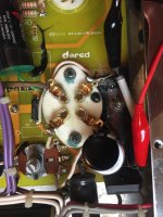
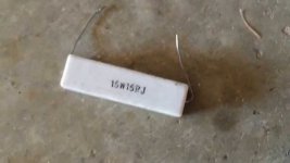
This is a photo of the resistor when it still had part of the case on it.
It almost looks like a ceramic white one (photo from the internet).
Weird also that the two potentiometer do not look the same.
I would be curious to see how a stock Dared DV-300B looks like to spot which modifications have been done (or even better find the original schematics).
The previous owner, which owned the amp for 8 years apparently, and bought the amp already in this state (I believe).
This is a photo of the resistor when it still had part of the case on it.
It almost looks like a ceramic white one (photo from the internet).
Weird also that the two potentiometer do not look the same.
Attachments
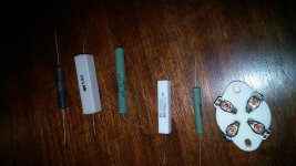
As a size comparison, from the left the black resistor is a 13 watt dale, the large white and the large green are 20 watts and the two smaller ones beside the socket are 10 watts. The ohm values are different but that doesn't affect the size.
The two Dared amps that I've seen used the green wirewound type that were 15 watts if I remember correctly.
If the resistors in your amp got hot enough to crack the ceramic and burn the board, I'd say you have other problems besides replacing the resistors. It does appear that the resistors that smoked were 10 watt types and they were probably dissipating over 6 watts so the margin wasn't large enough but that's not the only issue.
I would look at the caps as well as one has a split casing. I haven't seen a cap fail like that before, they usually either leak out the bottom or pop the top.
Attachments
Thanks for the photos comparing the size.
This evening I will test again the resistor with one leg unsoldered, and I will also test the voltage drop.
I will check the capacitor as well. From having a look at the capacitor, it does not look like leaking or exploded, but rather the plastic which wrapped the metal capacitor may have melt because of the heat dissipated by the resistor.
If I buy a resistor with higher wattage rating, would it run cooler this time, granted nothing else is broken in the amp?
Which Dared did you see?
The heat generated will be the same (no free lunch) but the resistor will be larger and be able to disipate the heat better. Once again, if your amps smoked two resistors like that, they need a good going over before anything else.
The other Dared amps I have seen the insides of were an EL34 type and a 3 box 300B. Not the same as yours but manufacturers don't buy different types of parts for similar amps usually. They buy in bulk to get price breaks and not carry inventory. I also had a quick look online and didn't see any with V-caps either. Your amps may be "special".
The other Dared amps I have seen the insides of were an EL34 type and a 3 box 300B. Not the same as yours but manufacturers don't buy different types of parts for similar amps usually. They buy in bulk to get price breaks and not carry inventory. I also had a quick look online and didn't see any with V-caps either. Your amps may be "special".
I actually tested the resistor, in circuit, again and they are 0.842K ohm..., so 842 ohm...not 83k...
About testing the voltage drop, just to make sure:
- I set the multimeter to DCV
- connect red probe to one leg of the resistor
- connect black probe to the other leg of the resistor
- turn on the amp with the tubes inside
On the multimeter it should give me a value in volts (or millivolts) and that's the voltage drop?
So they're probably 820 ohm resistors. Standard decade value.
You really need to have the amp looked over to ensure that it's not a fire hazzard. It's your house and your insurance won't cover it if the amp was modified.
And the cap that was hot enough to melt the plastic casing needs to be replaced on both sides of both amps. Even if it was a 104C cap it was over that to melt the plastic.
@zelgall: i think the caps melted the plastic because the resistor next to them was overheating. Whatever close to the resistor has been melting, that includes the PCB and the plastic on the nearby caps. At least, that's what I hope. But I will be checking those caps anyway.
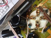
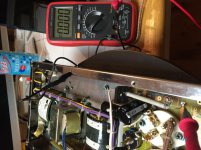
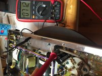
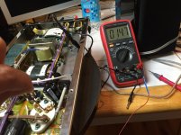
I have checked the voltage drop:
With the amp on, DCV on multimeter, black probe on the chassis:
- Red probe on the resistor leg (closer to black capacitor) measures 71.2v
- Red probe on the other resistor leg (closer to 300b socket) measures 0v.
Same on the resistor on the other side (70.2v one leg, 0v other leg).
If I take the voltage at the 300b socket pin closer to the resistor, voltage is 425v.
Temperature wise, both resistors are 140-150 degrees celsius. Both capacitors (with melted plastic) are instead 37-39 degrees celsius.
What's wrong with this voltage drop? Is it normal that one leg of the resistor is 71v and the other one is 0v?
Attachments
Last edited:
- Status
- This old topic is closed. If you want to reopen this topic, contact a moderator using the "Report Post" button.
- Home
- Amplifiers
- Tubes / Valves
- Which resistors to replace burned ones in Dared DV-300b monoblocks