John you can't force a square peg into a round hole
John,
It's simple... it is class A only because it is only one tube. Therefore there is no way to force it into AB.
MagneQuest only uses Cobalt on the most expensive transformers.
Sowter and MagneQuest typically use iron sometimes nickel but mostly iron.
Have fun,
Gordon
John,
It's simple... it is class A only because it is only one tube. Therefore there is no way to force it into AB.
MagneQuest only uses Cobalt on the most expensive transformers.
Sowter and MagneQuest typically use iron sometimes nickel but mostly iron.
Have fun,
Gordon
I think, I may be thinking of a different method for A/B operation. I'll describe the problem I'm having, see if you can see any mistakes.
In this example, bias is being set by an outside source, the cathode is connected directly to B-
Svetlana EL34
As per Svetlana's data sheet on the EL34, the maximum current that the EL34's cathode can supply is 150ma. So, if the cathode is already supplying 150ma, even if the grid signal continues to move positive, the current passing through the cathode will not increase, so the peak of that signal is not amplified.
The maximum power the EL34's anode can dissipate is 25W. Using a plate voltage of 25W / 0.150ma = 166.7V means that when the grid is driven to 0V, or into a positive amount, the cathode will be supplying the maximum amount of current it can. Any extra current draw off the cathode supply by the grid will be going through the grid resistor anyway, not to the plate.
To increase cut off distortion, without destroying the anode, the plate voltage needs to be decreased a bit. So, say we set the plate voltage at 160V. The cathode can't supply any more than 150ma. To reach 25W, the cathode would need to supply 156ma with a plate voltage of 160V, so there are now 6ma spare before the plate will be dissipating too much.
So, by decreasing the voltage, a point is reached where by the cathode can no longer supply the current needed to amplify the entire signal at the grid, because the cathode is delivering 150ma before the grid ever reaches 0V. Since the plate voltage is low, the dissipation is below the rated 25W for the tube.
On Svetlana's performace graphs, a 160 - 170v plate voltage at 150ma corresponds to a cutoff point around -8 or so volts at the grid. Anything above this won't be amplified, since the cathode can't supply any more than 150ma. If you print the graph out and draw a line on it for the maximum anode dissipation, this point is quite easy to find.
For the cathode to, virtually, stop conducting, a grid voltage of around -30 or so needs to be obtained.
-8 to -30 is about 22V of grid voltage swing. 22 / 2 = 11. So setting the grid to -19V would produce the mid point for an asymetical signal at the grid.
If a signal over 22V enters the grid, in it's positive cycle, it will cause the cathode to dissipate the maximum amount of current it can before it reaches it's peak. In the negative cycle, the signal will cause the cathode to 'stop' conducting.
I've been quite rough with calculating these numbers, they're not verse, or even particularly accurate, but they should give an idea of why I'm confused.
I say the cathode 'stops' conducting because those grid lines never meet the X axis, they all end at 0V. Once the grid starts moving beyond -30V, cathode current can be measured in uA. If you don't draw the line somewhere, you could say that all Class AB stages could be considered A, since the chances of a grid ever stopping 100% of the electrons floating round in a tube is laughably remote.
The way I understand it, cathode current limits are determined by how well the cathode can emit electrons, not the maximum power rating of the tube. In my understanding, the cathode is not damaged when supplying 150ma of current, it simply can't supply any more. Damage is done only when the electrons are accelorated into the anode by the plate voltage.
This seems way too simple, and I feel like I must have made a very big mistake somewhere. But looking at Svetlana's datasheet, I don't see why the tube would not distort under these conditions.
I'm ready to feel stupid.
eeka chu said:This seems way too simple, and I feel like I must have made a very big mistake somewhere.
I hope you're sitting comfortably. The reason that EL34 doesn't show any grid curves with positive voltages is that this valve is not normally operated in this mode. But it could be.
Similarly, the maximum cathode current limit of 150mA is not the most that can be dragged from the cathode, but the maximum current that can be drawn without damage.
Regarding your understanding of Class A vs B.
Imagine you had a single amplifiying device that had to deliver a 100Vpk-pk sine wave, and that to do this it operated at its limits of internal power dissipation. This is Class A
Now imagine that you had two of these devices, but this time, you use one device to amplify the positive half-cycle that swings from 0V to +50V, and the other device to amplify the negative half cycle from 0V to -50V. To recover the original waveform, you would add the outputs of the two amplifiers together. Further, you could switch each device off when it wasn't needed to amplify its half cycle. Averaged over an entire cycle, you would have (very roughly) halved the heat dissipated within the device. You will also have realised that if each device is only swinging 50V, the entire composite amplifier could be driven harder, so that each device could swing 100V, and the entire amplifier would now swing 200V. This is Class B.
Note that Class B relies on two devices. Or, to put it another way, single-ended amplifiers must be Class A.
If you pass grid current (by driving the grid positive), this is indicated by adding "2" at the end. Thus, it is possible to make a Class A2 amplifier. Or a Class B2, for that matter. Theres's a lot more that could be said on this topic, but it's all covered in the 621 section at your local library.
I hope you're sitting comfortably.
Yep!
The reason that EL34 doesn't show any grid curves with positive voltages is that this valve is not normally operated in this mode.
I was perhaps a bit off track including the part about positive grid voltages.
Similarly, the maximum cathode current limit of 150mA is not the most that can be dragged from the cathode, but the maximum current that can be drawn without damage.
Once the grid reaches 0V, the plate no longer tries to pull anymore current towards it right? To the plate, the cathode is clear to it, the grid is no longer having an effect on the electrons leaving it.
So, the only element that can now draw any greater current from the cathode is the grid it's self. In a worse case situation, say the grid swings 10V positive for a period of time. While the grid is closer to the cathode than the plate, it's voltage is less than 10% of that present at the plate.
With a 5.6k resistor on the grid, a drop of ten of volts across it is only going to allow one or two mA of current to flow out of the grid, assuming the grid is a direct short circuit to the cathode.
but the maximum current that can be drawn without damage
This is what made me curious in the first place. Eddie Van Halen was very famous for using a Variac to change the plate voltages in his Marshall amplifier. While his amplifier used a PP output stage, the idea seems to be similar. He would lower the plate voltage and increase the cathode current by resetting the bias so that the tube continued to dissipate their maximum rating, but at a higher current.
A lot of guitarist who do similar things report having shorter tube life spans. A lot of them also fail to rebias their amp correctly. I don't know if it happens in audiophile circle, but they describe it as running the tubes 'hot', as opposed to 'cold'.
There are two groups of people who do this. The first group are not particularly interested in electronics, and the 'hot / cold' terminology kind of reflects this. Rather than changing the parameters of the valves with their dissipation as a constant, they just decrease the bias voltage and leave the plate voltage constant. So the valves get much closer to their dissipation limit.
What was particularly different about Eddie Van Halen's method is the reduced plate voltage. Meaning that he was bothered about dissipation, and was instead trying to increase the cathode current a great deal, without expecting the plate anodes to go beyond the dissipation limit.
Eddie Van Halen's stock amplifier, a Plexi, wasn't particularly distorted even when it was running with the volumes at 11. It was the 100W model of the Plexi's that Jimi Hendrix used. After the bias adjustment however...
 it became possibly the most incredible sounding guitar amplifier ever!
Again, as I'm quite new to amplifiers that are designed -not- to distort, I am unsure of the tube life one should expect from a valve like a 300B.
For a guitar amplifier, valves are considered as consumable. If you run you guitar full out, a set of tubes will last 6 - 18 months. As you can probably guess, almost no guitarist buys NOS tubes unless they're going to be run in Class A.
So a new EL34 every 6 or so months isn't so bad when most guitarists have to buy a quad of matched EL34's, and then another 5 or more preamp tubes in the same time span.
Theres's a lot more that could be said on this topic, but it's all covered in the 621 section at your local library.
Reading my own messages, it makes me feel like I'm trying to right the world on SE amplifiers. That's not the reality.
My problem has been that every site or reference I have read has told me that an SE stage must operate in Class A. Some even went as far as saying that, if an amplifier runs in Class A, it will almost certainly be an SE stage.
Everything has been in reverse and assumes that if you're using an SE stage, you require Class A operation and that you will need a NOS tube to last years, due to it's replacement value.
I'm not kidding you at all, I -seriously- spent an hour or so on google doing searches for 'Single Ended Class A only because', 'Why Single Ended Class A' and 'Single Ended only in Class A'.
I found hundreds of sites telling me that SE stages run in Class A, even detailed definitions of the classifications. Not a sinlge page, genuinely, explained why a SE stage couldn't go into Class AB.
It's counter logic to that which high fedelity designs are specified for.
With all this in mind, I also fail to see why a tube set up in such a way would not deliver a considerable amount of it's full plate dissipation.
As I've mentioned, I've actually seen one particular guitar amplifier that uses an EL84, a 12W valve, setup to output 11W plus into an SE stage. And a number of guitarists have built and played this amplifier.
The main problems I can see so far with running a valve with a dissipation over 10W in an SE stage are, A. The parts are very tricky to find, and B. The parts are usually very expensive.
Note that Class B relies on two devices. Or, to put it another way, single-ended amplifiers must be Class A.
I don't agree. A single valve in a PP can not operate in Class A or AB on it's own, as it only swings over one side of the 0V line, as you have stated. So it can not amplify the signal present at the grid for more than 50% of the signal's cycle. This is, of coarse, assuming that the input signal is a sine wave form passing through both positive and negative signs. If the input where a pulsed DC source, present in only one sign, then a single valve of a PP stage could, theoretically, operate in Class A or AB.
But this is not to say that an SE stage -must- operate in Class A because a single valve in a PP stage can not.
The fact that a SE valve swings to both sides of the 0V line of a signal would not appear to fix it to Class A only operation. Class AB stages conduct for more than 50% of their input signal, and less than 100%. As far as I am aware, this is regarless of whether the signal postive and negative, it is simply an operational duty percentage. As per the RCA definition of Class AB operation. A number of other texts also support this definition.
As a whole, the output stage of a PP stage may, theoretically, operate in Class A1, so long as there is absolutely zero cross over distortion. Whether that can be made possible in reality for a particular stage is another matter. An entire PP stage may also operate in Class AB, also, as you have said.
In a recent thread I was told to not blindly follow one particular text. I still have not been shown why it is impossible for an SE stage to run in AB mode. So I'm not following the advice that this is the case at risk of being called someone who does not listen to others. SE Class AB operation may not be beneficial for high fedelity audio, or a valve's life span, but this is far from the suggestion that it is an impossibility.
I would like to thank you EC8010 for actually replying to my recent questions along side Andy and Gordon. Considering the number of valve audiophiles on this board, it has suprised me that a question can be read by multiples of people and yet so few feel confident enough to answer it.
I would like to thank you EC8010 for actually replying to my recent questions along side Andy and Gordon. Considering the number of tube audiophiles on this board, it has suprised me that a question can be read by multiples of people and yet so few feel confident enough to answer it
We aren't all engineers you know
In the end it is suprising how little you have to know to build a good sounding tube amp. As opposed to having to answer a question or two on it...
To throw in my 2uF's worth..
Have you seen this site before? http://www.ax84.com/home.html
the thing I like about it is you can actually listen to music played through the various iterations of the amp.
Cheers,
Bas
We aren't all engineers you know
I'm far from understanding most of the complex ideas also. I have been getting quite angry these last few days as I've been moving from site to site.
I've spent literally hours of my time reading through 'Audiphiles' notes only to find that not only do they not explain themselves, but that they also present some very questionable reasoning, that they then expect you, as the reader, to willingly accept. Regardless of how insane it sounds.
I am far from aiming any anger at guys on this board who are trying to help me. But I'm getting tired of walking away from a monitor, four hours later, with a headache and knowing almost nothing more than I did to start out with.
Some of the stuff I'm reading on such sites is so disappointing that I'm really quite lost for words.
In the end it is suprising how little you have to know to build a good sounding tube amp. As opposed to having to answer a question or two on it...
More people enjoying music everyday can only be a good thing! People playing music themselves, excellent! 'Audiophiles' talking about the tone of their power cables, a joke!
Have you seen this site before? http://www.ax84.com/home.html
The AX84 project! I've been visiting the place for so long I can't remember when I started. This, for me, is the way electronics and audio should be combined. An idea worked out in theory becomes something that you can use and enjoy playing through, without worrying about mechanically tuning the power cable with polystrene cups.
It always amazes me that guys who've never soldered before can pick up such ideas, build a guitar amplifer and then produce an incredible level output quality from it. Music is so defined, many times over, by nothing more than the players feelings, and they come free with a body.
I am far from aiming any anger at guys on this board who are trying to help me. But I'm getting tired of walking away from a monitor, four hours later, with a headache and knowing almost nothing more than I did to start out with.
Yes...I know..in my book you already have guru knowledge

You just have learn who to listen to..(mostly yourself )
Engineers don't know everything (but do come in handy from time to time
)...I remember guys fresh from university (electronics) refusing to believe coax digital link (generally) sounds better than optical (toslink)..I mean REFUSING to believe. But then again they don't believe but "reason"...then again there is a good engineering answer why coax OFTEN sounds better.End of rant..
Anyway in the end you have to do what works for YOU.
That is why I never get into an argument on DIY... why should I knock what works for someone..
That includes the tone of their power cable You won't hear in my system..but I have heard how little upside down pyramids made a HUGE difference under a CD transport in dht amp/single driver setup. Hearing truly is believing.
Good luck on your quest!
Cheers,
Bas
Edit:
Mmm...just read my post again..it's getting late ...starting to show signs of halojoy type o posting.
Perhaps you need Mr Muscle...
eeka chu, you clearly have a conceptual block somewhere on the Class A vs Class B issue. This can often happen, but the tricky bit is finding where the block is. I am sure that when the block is satisfactorily explained, you will suddenly understand the whole issue, and wonder why it was so hard initially.
Perhaps a graphical method such as loadlines might put you on the right course to crack the problem. Loadlines have been discussed a number of times on the forum, so a search will dig them out. Alternatively, I'm a great believer in letting the subconscious do the work. Perhaps leaving the problem alone for a day or two will suddenly result in the metaphorical lightbulb switching on for you.
Meanwhile, undistorted single-ended audio requires Class A. Push-pull audio can choose to use Class A or B, but usually uses somewhere in between (Class AB).
Hi,
Too many Neil Young sessions?
Cheers,
A = Class A (least efficient)
B = Class AB
C = Class B
D = Class C (telephony, sometimes speech)
Suffix 1 behind a class of operation means the grid isn't drawing current, suffix 2 indicates grid is driven positive and hence will draw current.
Was that the block?
Too many Neil Young sessions?
Cheers,
A = Class A (least efficient)
B = Class AB
C = Class B
D = Class C (telephony, sometimes speech)
Suffix 1 behind a class of operation means the grid isn't drawing current, suffix 2 indicates grid is driven positive and hence will draw current.
Attachments
Not quite. I realise that the only way to produce an undistorted output is by the use of a Class A process. The classification of processes isn't a problem.
My confusion lies in why so many people believe that a valve in a SE stage is not able to distort. If biased to a particular voltage the valve could be made to operate in Class B or even C, whether it's desirable or not. All that need be done is the bias set so negative, or positive, that only the very peaks of one sign are amplified, and by doing so 50% or less of the input cycle is being acted on. Again, assuming the input is a sine wave moving through both signs.
For a high end audio system, distortion is removed at every opertunity. Class A processes are desired. That's not the same as saying that a stage won't enter Class AB purely because it is not desired.
Class A guitar amplifiers sound like very loud acoustic guitars. Guys like Stevie Ray Vaughn use such a sound. His music is often clean Texan blues. Anything from the very softest blues to death metal, however, almost always a distorted, AB, process.
This is, again, where guitars and high end audio seperate. To someone designing a high end audio system, any distortion is bad distortion.
For a guitar amplifier, one form of distortion if not the same as another. The gritty electric sound of lead guitars is created by clipping the peaks of the wave forms, distortion. The rise time of a valve based rectifier smooths the notes into each other. This too is distortion. But while some guitarist like it, an equal number do not, as the articulation of the music is somewhat impaired.
This perhaps help explain my reasoning.
I am beginning to question if the idea of an SE stage only ever running in Class A has only become so set in stone due to it being the most commonly desired method, not a reality.
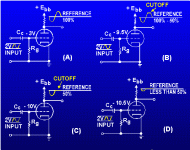
Hi Frank!
Neil... Young...?
That's the first picture I ever saw of process classification!
Isn't it from the Naval Electrical Engineer's Manual? Before reading the Engineer's Manual, I read a site specifically related to valves that may have had that piccy on it. It wasn't very well organised.
Thanks for the email! I spent an afternoon, last week, reading about tangential tone arms running on air bearings. Fun, fun, fun stuff!
Too many Neil Young sessions?
Neil... Young...?
Suffix 1 behind a class of operation means the grid isn't drawing current, suffix 2 indicates grid is driven positive and hence will draw current.
That's the first picture I ever saw of process classification!
Isn't it from the Naval Electrical Engineer's Manual? Before reading the Engineer's Manual, I read a site specifically related to valves that may have had that piccy on it. It wasn't very well organised.
Thanks for the email! I spent an afternoon, last week, reading about tangential tone arms running on air bearings. Fun, fun, fun stuff!
Gotcha! Of course a Class A stage can distort. But when discussing Class A vs Class B etc, we always assume perfect device linearity to avoid muddying the waters. (You just don't want no Muddy Waters.)
If we don't bias a single-ended stage correctly, it will distort. It won't be Class B, because it doesn't have another device to switch over to, just an inappropriately biased single-ended stage with no concessions to linearity. Not Hi-Fi. Might be useful for guitar.
A typical Class A triode power stage (biased appropriately for Hi-Fi) produces between 5% and 10% distortion, which is mostly 2nd harmonic, although harmonics up to 6th are generally measurable. A Class A pentode power stage typically produces rather more distortion, mostly 3rd harmonic. Both of these stages produce distortion because of nonlinearities in their transfer characteristic.
Clipping is caused by operating a device beyond its linear region, and causes odd harmonics.
If you operate a device near cut-off, it becomes nonlinear, and musicians' (valve) amplifiers use this to produce even harmonic distortion. By juggling gains and levels, it becomes possible to strike a balance between odd and even distortion. This is why musicians' amplifiers have so much gain, and so many gain controls.
Hello John,
Just pulling your leg...
Actually I adore Stevie Rays' guitar playing, especially when he covers the great Jimi H.
Anyways, here's where Abraham found the mustard:
TPUB.
Enjoy,
Neil... Young...?
Just pulling your leg...
Actually I adore Stevie Rays' guitar playing, especially when he covers the great Jimi H.
Anyways, here's where Abraham found the mustard:
TPUB.
Enjoy,
PENNY DROPS....
Hi,
Ah, ah...I had no idea it was you.
BONUS...
EC8010,
Admit it, you saw it coming from a mile away didn't you?
Cheers guys,
Hi,
Thanks for the email! I spent an afternoon, last week, reading about tangential tone arms running on air bearings. Fun, fun, fun stuff!
Ah, ah...I had no idea it was you.
BONUS...
EC8010,
Gotcha! Of course a Class A stage can distort.
Admit it, you saw it coming from a mile away didn't you?
Cheers guys,
Having a run at Class designation
Ok, gonna have a try at explaining the amplifier Class business - this is what works for me, and I reserve the right to be wrong.
Imagine a lightbulb. It has a switch. The "signal" that one lightbulb produces is light. Turn it ON and OFF in your mind a few times. Light when it's ON, Dark when it's OFF. Just one bulb. Therefore: If the signal is present, that one device must be ON.
This is the kernel of Class A, as it applies to Single-Ended operation: If there is light, then the bulb is ON, because there is only the one bulb.
Leave bulb #1 turned ON in your mind's eye.
Now imagine a second lightbulb, adjacent to the first. It is wired seperately, with it's own switch. Imagine that #2 is OFF.
Now turn ON #2. Both lights on.
Now we're still running in Class A, but we're no longer single ended. If both bulbs are ON all the time, it is still Class A. The drawback is that we're wasting a lot of power, because we have 2 bulbs ON.
Say we're not willing to spend the power to keep both lights on all the time. Perhaps we could turn them ON and OFF in an alternating fashion...
So for starters, reach over slowly in your mind and turn OFF bulb #1. Wait a moment, and then turn it back ON. They are both ON as we reach over and turn OFF #2. Wait a moment, and then #2 back ON. They are both ON again. Reach over, turn #1 OFF. Repeat cycle. While a bulb is off, think about what the other one is doing - it's still on, so there is no discontinuity of light.
This works pretty well; we are inputting less total power, and the individual devices are working less than full time. Sometimes both bulbs are ON, because you need to move your hand between the two switches. The rest of the time, one bulb is ON. At no point is it dark, because we leave both bulbs on while we move our hand between switches.
This is Class AB - we are sharing the load between two devices. When both are ON, we're in Class A, but because we are turning the bulbs off sequentially, there is some non-Class-A time in there - Thats the Class B part. Taken as a whole, we are spending some time in both classes, hence the combined name.
Now imagine that you could turn one bulb OFF at the exact instant you turn the other one ON. This time, only one bulb is ON at a time, but because we alternate them so fast, we can't distingush any OFF time. That's pure Class B.
If we were to alternate the two like we did for AB, with a bit of overlap, but instead of leaving both ON, we left both lights OFF - That would be Class C. But in practice, we'd never do that because we find the flashing unpleasant.
To understand Class D, find someone else to explain it.
I've intentionally ignored output power ratings, because the lightbulb metaphor doesn't work there. Likewise the notion of a waveform, with notions of positive and negative excursions. Those are distractions. Class only designates when the devices are conducting signal relative to a given interval. The lightbulb metaphor is to make you forget about all the tube specification details and trigonometry classes you don't remember.
Hope that helps (more than it hurts, at least)
Andy
If we don't bias a single-ended stage correctly, it will distort. It won't be Class B, because it doesn't have another device to switch over to, just an inappropriately biased single-ended stage with no concessions to linearity.
Tell that to everyone, (that it is not class B using only one device) who built single ended class AB or class B stages for RF.
Of course it is possible to build a single ended class AB, B or even C stage for Audio but it is not done to the simple reason that the tube, (or transistor) will be cut off during one part of the envelope giving gross distorsion. Single ended class AB, B or C stages are however quite common for RF.
Class A, AB, B or C does not have to do with number of devices used it only describes how the device is biased.
Franks mail showing the different classes shows what would happen if someone built a single ended audio stage that didn't run in class A.
Regards Hans
Class A, AB, B or C does not have to do with number of devices used it only describes how the device is biased.
This is an excellent point, one I didn't pick up on and make earlier.
Classification of an A - C system does not take into account whether or not there is one device, or thirty. Whether they're PP or SE, or even the polarity that the devices amplify through.
The only criteria within the system classifications A - C is, for what percentage of their input does a system operate?
Class A1 - 100% of the input is amplified, a practical impossibility in reality, unless you can control billions of electrons per second without loosing a single one. No grid current is drawn. Again, questionable in reality. However, reasonable lines have to be drawn somewhere.
Class A2 - Same as A1 but grid current is drawn.
Class A/B1 - Less than 100%, but more than 50%, of the input is amplified. No grid current is drawn.
Class A/B2 - Same as A/B1 but grid current is drawn
Class B - 50% of the input signal is being amplified.
Class C - Less than 50% of the input is amplified, but amplification still takes place.
Class D and on - Not really important at the moment.
Imagine a lightbulb. It has a switch. The "signal" that one lightbulb produces is light. Turn it ON and OFF in your mind a few times. Light when it's ON, Dark when it's OFF. Just one bulb. Therefore: If the signal is present, that one device must be ON.
This highlights a point about PP stages. The time it takes you to move your hand from switch one to two is effectively very similar to cross over distortion in the phase splitter of a PP amplifier.
If everything else about the system was perfect, if the valve amplifying the positive cycle was set to turn it's self on and off just before the 0V line, not directly on it, as only theory allows, the room would go dark for a fraction of a second as the positive valve was getting ready to switch on.
You could cheat and have one valve remain on for a fraction of a second past the crossover line while the other was switching on. This would cause that particular valve to operate in Class AB, as it is amplifying more than 50% of the entire system's input. And it's input would have to posses the information to allow it to do so, it would have to be more than 50% of the -entire- system's input singal. Which could then raise questions about what Class the original valve it's self was operating in depending on how much of this information was present and how much of it the valve amplified. In effect, the phase splitter would have to over shoot if you like. And the tube would have to be able to amplify this over shoot.
In this case, the entire system would now almost certainly operate in Class A, but it would have a lot of cross over distortion.
In the real world. Class A operation is a virtual impossibility, in a standard valve, according to field effects and the shear number of electrons in use. Electrons have notoriously weird properties due to them being so deep in the quantum domain. I believe, not even limited to a form of teleportation during entanglement. Managing to force every single electron to go from the cathode to the plate of a normal valve would be seriously impressive.
The problems occur since perfectly even distribution in a real world system is a near impossibility, choas theory doesn't permit it. Futher, by raising the order of a system, you increase the chance of that order being undone. This is called the Entropy of a system. High order entropy systems require high densities of information or energy. Heisenberg's principle says that a system will oppose such an increase at a specific point in space and time.
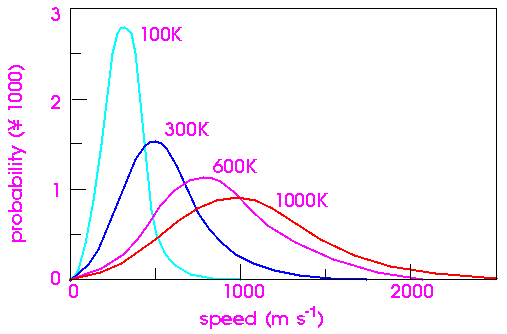
These Maxwell Boltmann curves can be found almost everywhere in the universe. Whether it's the temperature of your coffee or the social interactions of a group. They're such a powerful symbol of the universe. And very organic in nature, not linear.
So anyway...! While it's really pushing it to start saying, no Class A amplifer will ever operate in true Class A in the real world 100% of the time, a PP stage perhaps makes this slightly easier. Because, as you have pointed out, you must purposely introduce a cross over point, futher increasing the probability that a mistake in switching will be made.
To understand Class D, find someone else to explain it.
That's what the Solid State forum is for right?
I got your email on parafeeding. The diagram & table are definitly useful for quickly comparing one method to another. I particularly like the notes on voltages and values in the table, which should help save a lot of time. Thanks!
Gotcha! Of course a Class A stage can distort.
I'm not sure what you're saying. Whether you see what I mean, or if you've found a mistake in my reasoning. Any valve stage can move to any Class, A - C, dependant on how it's processing stage is set. Earlier on in the thread I suggested running a single valve in an SE stage close to it's maximim dissipation.
I was told that not only was this not possible, but that dissipation would be less than 50% at most.
Had I not persisted, I would now believe that an SE stage forced a valve to operate in Class A mode, and that any other Class was an impossibility.
After many solid hours reading through audio websites, I found the same statement over and over again, with no explanation.
The reality is, a SE stage will run in any Class A - C that it is set to. It's much easier to make a PP stage run in Class AB, if it ever runs in Class A in the first place right?
, but a cathode can only emit so many electrons per second due to it's size, coating and temperature. I don't believe plate voltage has a great effect on the rate of emission, not nearly as much so as the other properties. Electron emission is due to electrons within the metal possesing enough energy to break their electrostatic bonds and move into a fluid like state at the metal's surface. Like I say, those Maxwell Boltzmann curves appear everywhere. And here is no exception. A specific number of electrons at a given temperature posses this energy, and it is far from 100%. It won't be Class B, because it doesn't have another device to switch over to
It doesn't matter how many devices there are. If the valve is biased such that it only amplifies 50% of it's input, it is operating in Class B. It doesn't need another device along side it to amplify the rest of the signal for it, it's self, to run in Class B. In this layout, the -entire- stage is Class B, and this single valve is operating in Class B.
The only reason a Class B stage 'requires' two processing devices is if you would like to achieve a higher amplification duty percentage. With only one device in Class B, the stages output will be Class B and no higher.
Since Class B is set at as a 50% duty cycle, pairing two processing devices, to complement one another, produces a 100% duty cycle.
Class A output may now be produced from the -entire- stage, given that the valves are set to perfectly switch over.
For the -entire- stage to now move into Class AB, one valve, at least, will have to move into Class C, and amplify for less than it's 50% of the input cycle. That could be because too much is being expect of the tube it's self, or that the device switching it is not switching it perfectly with the polarity changes in the input signal.
This is a similar way of thinking to describing a SE stage as only operating in Class A. It doesn't. It's just the most common desire. You only think of a Class B stage operating with a pair of devices because you usually want to produce a higher Class than B at the output of an Audio circuit.
To a PP stage, you can have a different perspective on how you view the Class of a valve. If you consider the input signal directly into the system it's self, each valve operates in Class B, or even C.
If you now consider the same set up, but this time look at the input signal to each tube, each valve can operate in A - C. It's input is not the same as that which goes into the -entire- system, or even the other valve. If it amplifies 100% of it's input, to that particular valve, it's operating in Class A. To the -entire- system, it's operating in Class B. Since the -entire- system knows that, that one particular valve is only being fed 50% of the -entire- input signal. The valve does not know this. It only see's what's presented to it for amplification.
If you operate a device near cut-off, it becomes nonlinear, and musicians' (valve) amplifiers use this to produce even harmonic distortion. By juggling gains and levels, it becomes possible to strike a balance between odd and even distortion. This is why musicians' amplifiers have so much gain, and so many gain controls.
Eddie Van Halen took this a step further in most of his playing. When you play a string on a guitar, touching it directly in the middle fractures the note into a greater percentage of it's second harmonic. You can go on but once you reach the third harmonic it starts being tricky to make it sound, and it's also very quiet.
Compared to guitar's string on it's own, fracturing a note into such a greater percentage of harmonics produces a very interesting sound. There are many other ways to set up artificial harmonics by playing the string in a different way.
Ah, ah...I had no idea it was you.
Those bearing's look so expensive! I know chemical and biological labs use porous ceramics for air bubblers in their experiments. Without reading their site futher, I'm guessing this idea is similar. I'll be interested to see just what kind air support needs to be used with these bearings.
When considering Class AB etc, it's much better to think in terms of conduction angle (time, or duty cycle), than percentages of current (amplitude). The classes are defined by the time that they conduct. When a push-pull amplifier is biased into Class AB, both devices conduct for more than 180 degrees, causing an overlap where both conduct. The reason for this is to reduce crossover distortion as the waveform crosses over to be handled by one device, then the other. Crossover distortion is nothing to do with phase splitters, it is a direct consequence of imperfect switching in a Class B or AB push-pull stage.
Agreed, the classes have nothing to do with the particular device type, but as far as audio is concerned (and this is the diyAudio forum), only in a push-pull amplifier do we have the freedom to use anything but Class A. If you want the output to look anything like the input, a SE amplifier must be Class A.
Agreed, the classes have nothing to do with the particular device type, but as far as audio is concerned (and this is the diyAudio forum), only in a push-pull amplifier do we have the freedom to use anything but Class A. If you want the output to look anything like the input, a SE amplifier must be Class A.
- Status
- This old topic is closed. If you want to reopen this topic, contact a moderator using the "Report Post" button.
- Home
- Amplifiers
- Tubes / Valves
- SE OPT's & Biasing