Apparently, my sketches were not uploaded, as I just noticed.... Second try then!
But in rereading Merlin's article on grounding I already got something of an answer on undesirable multiple connections on the chassis. Although it's still difficult for me to visualize the implications in 'routing schemes'. Still trying though.
If there are mistakes in my new diagrammes, please point them out....
Kind regards, Stef.
Ps.; as for Uunderhills questions concerning grounding I am not able to interpret the consequences for that in using battery power. Is it a very different approach? From what I guess is that there much less current ripples, ie. noise, in the returnpaths. How would one implement this?
Attachments
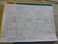
The implementation of a star ground, remote from where the signal needs to flow, leads to big Loop Areas.
Take your diagram at top left.
It shows the input arriving at the two pole socket.
Follow the Hot/Flow route to the first corner and down to that resistor. It flows to the star and then back to the cold/return at the input socket. See the size of that loop and how big it's area.
Now back to the input and follow past that first resistor to the second resistor, then through the resistor and on to the star. finally to return to the cold on the input socket. Again a big Loop Area because the star is remote from the flow and return. Then your third loop is through the third/grid resistor into the grid down to the cathode and then to ther star and finally back to the cold on the input socket. Yet again a big Loop Area because the star is located remotely.
Instead look at each loop and layout that loop with the minimum loop AREA. That requires paralleled wires that are VERY close together, The resistor in the loop should also lie right next to one side of the route.
Take the return cold line. Run it alonside the flow route to the first resistor, continue alongside that resistor. Attach to the bottom of the resistor. That loop is now complete. It has small Loop Area.
The second loop can be minimised by joining the bottom of the first resistor directly to the bottom of the second resistor. The cold route can again run alongside the second resistor.
You now have two loops both of which have minimised Loop Area.
Can you see where the thrid return route should go? Can you see why it can't have a tiny loop area? The glass envelope gets in the way. You have to accept a bigger loop area for this one, but you still try to minimise the AREA. Don't lave the cathode resistor out on a lonely limb. It needs the return route current to flow alongside it.
Keep going for every circuit connection. Identify the Flow and Return ROUTES. Place them right next to each other.
Last edited:
A resistor divider qualifies as a DC path to ground. I suppose I should re-write that rule as "rule number one is that the heater supply must not be left floating".
Merlinb,
So I take it, you are the author of the Value Wizard series.
Thank you for all your efforts, I have a number of your articles printed out
and are in numerous binders - especially the one on cathode follower and mu follower.
Think your wording was quite articulate and would leave it as is.
Stef,
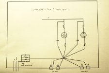
Think Andrew is quite right - some of the wiring in the diagram has taken quite the journey.
I've drawn a diagram that shows more of a physical layout.
The star ground node is quite near the input RCA shields, however, the amplifier by pass capacitors
should be able to reach the star ground node too.
The loop that I'm wondering about is formed by B+, the L and R amp and audio ground. I've made this loop quite small.
Attachments
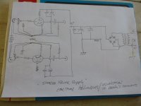
You need to identify how the B+ current returns to the source.
When you have hightlighted that route, you can then redraw the route to minimise the Loop Area. It will look very different to the way the sch is drawn.
Then you try to place your Power twisted pair to achive that LOW LOOP AREA.
You may find that you have two, or more, RETURN currents going back to the Source. You should minimise the Loop Area of EACH loop.
Hi Andrew, hi Uunderhill,
As a short reply, I am aware of the shortcomings in my sketches! Rather difficult to convey clearness... Those sketches were not meant as a physical representation but as a way in showing what points could be considered as 'nodes'. In an actual built I would try to join all the components that must be connected to the earth-star/buss. I would really aim for a complete 'compactness' of a build. And that is really hard, or impossible, to draw.
@Andrew, would it be possible to sketch your comments on Uunderhill's specific project?
Kind regards, Stef.
I consider this to be a big mistake.I would try to join all the components that must be connected to the earth-star/buss.
Instead treat EVERY connection between modules as a TWO wire connection.
Make all those module to module connections with very Low Loop Area wire pairs.
When all that is complete, then look at your sch and see if any single connection is missing. This could be a voltage reference connection that carries almost no current. There could be a few of these and these would all be taken separately to a common reference point.
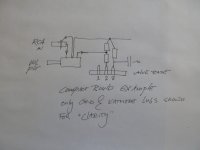
So I noticed a glaring mistake in my example diagrammes, I was planning to sketch a cathode follower and I stupidly drew the output from the grid...Aargh, those mistakes show my newbieness glaringly!
But here is a sketch in which I try to show how compact I would try to build. I really love to connect components and circuits just by the components needed, which is not always possible, but nevertheless a 'good thing'.
So I hope a 'small loop area' also comes from compact building. Is this correct?
Kind regards, Stef.
Attachments
I consider this to be a big mistake.
Instead treat EVERY connection between modules as a TWO wire connection.
Make all those module to module connections with very Low Loop Area wire pairs.
When all that is complete, then look at your sch and see if any single connection is missing. This could be a voltage reference connection that carries almost no current. There could be a few of these and these would all be taken separately to a common reference point.
Thanks Andrew! And I don't quite understand your words, I vaguely suspect a 'nomenclature' barrier... (whatever that is...)
In the 'compact' drawing I presented I hoped to illustrate my idea of very short routing and hoping that would be an answer to 'loop area'. And that is what I meant by writing 'join all the components that must be connected to the earth-star/buss'. And you see this as a big mistake, so should I have formulated it differently? To get it more clear, is a 'module' in your words a stage? because to me 'modules' and 'components' do differ...
Kind regards, Stef.
Ps. I still think a little sketch of your ideas would be helpfull as well....;-) (especially towards Uunderhill's project...)
But here is a sketch in which I try to show how compact I would try to build. I really love to connect components and circuits just by the components needed, which is not always possible, but nevertheless a 'good thing'.
So I hope a 'small loop area' also comes from compact building. Is this correct?
Kind regards, Stef.
Stef,
Interesting that you used an example for a volume control.
I've never really understood the idea of a volume control at the front of amp,
which attenuates the signal - only to be followed by an voltage gain stage,
which then amplifies the signal (and noise) again.
Dig a hole and fill it back up again.
To solve the problem, I see people put huge efforts into using a set of stepped resistors,
selected by either a rotator switch, or a set of relay switches.
IMO the real solution is to have a gain stage ==> volume control ==> buffer output stage.
But I'll leave that idea for the future.
The volume control I've used in this build, is most likely a carbon based variable resistor.
I'm not a fan of putting a carbon resistor in front of a voltage gain stage.
So rather, I'm going to use a stunt volume control, with a metal film resistor in series
and the variable carbon resistor in parallel.
Here is an interesting discussion concerning shunt volume controls.
Shunt Pot Volume Control for Better Sound and/or Gain Reduction - World-Designs-Forum
I am not advising spending silly money on metal film resistors.
The Holico's I buy are 26 cents each and the PRN's are 45 cents each.
After prototyping the shunt volume control, it seems that the area most sensitive to EMI
is between the series resistor and the Grid.
So I suggest keeping the lead lengths after this series resistor very short.
.
Stef,
To add, the old text book equation for resistor noise is an equation for thermal noise.
Vt = SQRT(4kTBR)
where:
Vt = the rms noise voltage
k = Boltzmann's constant
T = temperature(Kelvin)
B = noise bandwidth
R = resistance
However, a few years ago I was tinkering around with a MOSFET power amp
and couldn't understand why a metal film resistor sounded so much
better than a basic 1/4 Watt carbon resistor.
The thermal noise equation says nothing about the material the resistor is made from.
However, as it turns out, 1/f resistor noise is predominate in the audio bandwidth.
Selecting resistors for preamp, amplifier and other high-end audio applications | EE Times
Resistor Types - Does It Matter?
Again, I am NOT advocating people go an spend small fortunes on silly over priced resistors.
The Holco metal film resistors I like are 26 cents each ( about 0.18 Euros).
.
After reading up a bit, turns out one version of Holco resistors had mechanical problems.
http://www.diyaudio.com/forums/parts/6760-resistor-comparison-test-tantalum-3.html
I never had any issues with the version of Holcos I had.
Holco Resistors
Anyway, my point being was that I suggest using low noise resistors
before the first Grid and keep the lead lengths short.
.
http://www.diyaudio.com/forums/parts/6760-resistor-comparison-test-tantalum-3.html
I never had any issues with the version of Holcos I had.
Holco Resistors
Anyway, my point being was that I suggest using low noise resistors
before the first Grid and keep the lead lengths short.
.
The problem can then be overload, instead of noise. That is why designers need to think about gain profile.Uunderhill said:IMO the real solution is to have a gain stage ==> volume control ==> buffer output stage.
Excess noise is often associated with DC current. Note that carbon resistors can be a bit nonlinear - guitar people love this, but hi-fi people need to be wary.However, a few years ago I was tinkering around with a MOSFET power amp
and couldn't understand why a metal film resistor sounded so much
better than a basic 1/4 Watt carbon resistor.
The thermal noise equation says nothing about the material the resistor is made from.
That is why designers need to think about gain profile.
The voltage gain of this SSRP is approx. x 4.
I selected a low mu tube in order to keep the gain down.
However, its madness to attenuate the signal and then amplify it again.
I have not listened to this preamp yet.
However, its clear that if the volume control is followed by a preamp and then 30 dB's(?) of gain from a power amp,
then the quality of the volume control will have a significant impact on both the quality of the sonics and noise.
It seems that the track material for the ALP's volume control is metallised conductive plastic.
So at least it should sound better than a basic 1/4 Watt carbon resistor.
However, I suspect that good quality metal film resistors sound miles better.
Which explains why people go to the end of the earth to build stepped attenuators.
But the idea here would be to set the attenuation, slightly above typical listening levels, using quality metal film resistors.
Then the final listening level adjusted with the variable resistor.
.
OK, most electronics is mad.Uunderhill said:However, its madness to attenuate the signal and then amplify it again.
Is it clear? Maybe to those who design on the basis of what they read in magazines.However, its clear that if the volume control is followed by a preamp and then 30 dB's(?) of gain from a power amp,
then the quality of the volume control will have a significant impact on both the quality of the sonics and noise.
I suspect that many people who build stepped attenuators do so because someone else has told them that pots are bad for sound, or to gain bragging rights. It is clear that some of them don't understand what they are doing because they complain about clicks; not understanding that a switched volume control must see absolutely no DC.Which explains why people go to the end of the earth to build stepped attenuators.
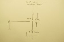
Here is the shunt volume control I decided to go with.
Hopefully, its OK to use the 24K not only for the volume, but as a grid stopper as well.
Using info from Value Wizard, the capacitance between adjacent pins, of a 9 pin tube socket, is about 1.5pF.
For a ecc86 tube Cgp ~ 1.5pF and Cgc ~ 3pF and the gain of this SSRP is about x 4.
Cin ~ (Cgc +1.5pF) + (Cgp + 1.5pF)( 1 + Gain)
Cin ~ 50pF
The 24K resistor, R vol and Cin form a transfer function.
Which I haven't looked at in 25 years
but its T(s) = R vol // Xc
................ -----------------
................ 24K + R vol // Xc
Hopefully, this does not cause any phase issues at the high end of the audio band.
The section between the 24K resistor and the Grid was far more susceptible
to EMR than the section between the RCA and 24K resistor.
So the 24K was soldered very close to the tube socket.
After finally being able to listen to the line stage today, its very quiet.
The volume needs to be cranked up just hear any buzzing through the tweeter.
But I may try adding some shielding between the RCA and 24K.
.
Attachments
Here is an interesting article about film caps.
Observing Inner and Outer Foil of Some Popular Capacitors – Jimmy's Junkyard
Even though film caps are non polarized, the idea is that the outside of the foil
is used as a shield for the inside of the cap.
So when a foil cap is used as a coupling cap, the outside of the foil
should be connected to the low impedance side of the circuit.
Single coil guitar pick ups use the same principle.
For the output coupling cap, I used Clarity Cap ESA's.
There was quite an audible difference when switching the shielded side of this cap around.
.
- Status
- This old topic is closed. If you want to reopen this topic, contact a moderator using the "Report Post" button.
- Home
- Amplifiers
- Tubes / Valves
- Star Grounding for a Line Stage Tube Preamp