For a typical direct coupled input triode to cathodyne arrangement (plate of input triode about 130V, B+ for cathodyne of about 400V) do I need to add any any extra protection (e.g. zeners) if I substitute the current triode cathodyne with a DN2540?
The MOSFET source will simply pull up to B+ at start-up time. As long as the source resistor can handle it, there should be no problem while the input triode warms up.
Last edited:
weeee! resurrection!
ok, while this sounds like the ideal way to deal with the PI for these pesky russian rod tubes with their directly heated cathodes, im still confused... can i use a fet with that internal freewheel diode or should i waltz on down to jaycar and find something without the internal diode? only running 150 or so volts on the rails...from memory. any suggestions?
my knowledge of sand is that it makes smoke, and magic happens when things arent glowing... that is all...
I don't think Jaycar has got anything with a high enough voltage rating. I ended up using an FQPF2N60C from Mouser but any of the usual suspects for source followers would be good (look for low and steady Crss and sufficient current and voltage rating).
All mosfets have an intrinsic body diode from source to drain but that is irrelevant in this application. It doesn't hurt to add a 12V zener from gate to source just in case.
All mosfets have an intrinsic body diode from source to drain but that is irrelevant in this application. It doesn't hurt to add a 12V zener from gate to source just in case.
IMO/IME, a protective Zener diode between gate and source is mandatory, not merely a good idea. At power on, before the tube starts conducting, the gate is at B+ potential and the source is at ground potential, which can lead to FET failure. Once the tube is conducting, the source will follow the gate and the FET is safe. This but 1 more instance of start up conditions being quite different from those in the "steady state".
Agreed. Aside from any start-up issues, think about what happens when you overdrive the output valves - grid current starts to flow on positive-going half cycles, clamping the voltage at the source of the MOSFET and keeping it from rising, while the MOSFET gate continues to be driven positive by the preceding valve. Under these conditions, it is extremely likely that the maximum allowed gate-source voltage will be momentarily exceeded, and that will be the end of your MOSFET. Poof!IMO/IME, a protective Zener diode between gate and source is mandatory, not merely a good idea.
I used a series-connected, back-to-back pair of 12V Zener diodes between gate and source, to make sure the maximum gate-source voltage couldn't be exceeded with either polarity, along with a series "gate stopper" resistor to limit current flow through the Zeners when they did their thing.
-Gnobuddy
Last edited:
too true, i forget about jaycars useless inventory. all good, a smps provides me with the svf2n60mj... now to figure out how to actually bias it... start at 1k and see how much smoke escapes i guess...I don't think Jaycar has got anything with a high enough voltage rating. I ended up using an FQPF2N60C from Mouser but any of the usual suspects for source followers would be good (look for low and steady Crss and sufficient current and voltage rating).
All mosfets have an intrinsic body diode from source to drain but that is irrelevant in this application. It doesn't hurt to add a 12V zener from gate to source just in case.
From the datasheet, this one is an N-channel enhancement MOSFET. This means that the source needs to end up at a lower voltage than the gate, so you can't use self-bias with a source resistor the way you do with a triode like a 12AX7.now to figure out how to actually bias it... start at 1k and see how much smoke escapes i guess...
This isn't a problem at all, you just have to bias it a little differently. For a cathodyne substitute, use a pair of resistors to set the gate at one-quarter of B+ voltage. In operation, the source will automatically settle to within a few volts of that; because you're going to be using it with a B+ of several hundred volts, the few volts difference between gate and source is utterly unimportant, so you don't even need to care exactly what Vgs is.
The only thing left is to connect the source to ground with a source resistor chosen to flow a millamp or two through the MOSFET, connect the drain to B+ with a same-value resistor, and add a "gate stopper" resistor to prevent radio-frequency oscillation, and an input coupling capacitor to block any incoming DC voltage from the preceding stage. And don't forget to protect the gate from excessive gate-source voltage with a couple of Zener diodes.
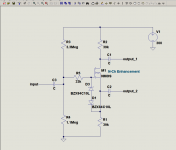
The attached schematic should do the trick. The 1.1 and 3.3 meg resistors set the gate at one-quarter B+, the 33k is the gate stopper, the 39k source and drain resistors give you a wee bit lower impedance than the 56k resistors Leo Fender typically used here (you can lower them further if you like, but the source-o-dyne will draw a bit more current from the B+ rail if you do.) Finally, the two 10-volt zeners keep Vgs within safe values.
You can change all the capacitor values to suit your amp and/or personal taste, of course.
-Gnobuddy
Attachments
Last edited:
see, that there nugget isnt mentioned anywhere...From the datasheet, this one is an N-channel enhancement MOSFET. This means that the source needs to end up at a lower voltage than the gate, so you can't use self-bias with a source resistor the way you do with a triode like a 12AX7.
for self bias, you want, i can only assume, an N-channel depletion mode mosfet. a device that is normally...um...on. sort of like a triode is.
anyway. theres a circuit to fiddle around with! i see exactly whats going on there. thanks.
")
Just to play devil's advocate, why not?Why such a large value for the gate stopper resistor?
Merlin Blencowe points out in his preamp design book that grid stoppers in most commercially manufactured guitar amps are usually ten to a hundred times smaller than optimal. Perhaps we are carrying over the same design flaw to MOSFET designs?I usually see 100 ohms to 1k.
Reasons to use a much larger gate stopper include:
1) There is no DC current flow to speak off in the gate stopper
2) Because the MOSFET is in source-follower mode (due to the large unbypassed source resistor), the internal gate-source capacitance is bootstrapped, and so appears at least ten times smaller at the input compared to normal values of Ciss. Because voltage gain to the drain is small (magnitude is unity), the drain-source capacitance isn't amplified by the Miller effect, either. So the input capacitance of a MOSFET used as a source-o-dyne is quite small, meaning here is also negligible AC current flow in the gate stopper at any frequency in the guitar bandwidth.
3) A nice big gate stopper resistor will provide a better guarantee that even a high-transconductance MOSFET won't burst into self-oscillation.
The only negative I can think of to using a bigger gate stopper is a tiny bit more thermal noise - but we're at an amp stage where the signal usually measures in volts, or even tens of volts, while the thermal noise from a 33k resistor is a couple of microvolts. So the thermal noise is 120 - 140 dB below the signal - utterly irrelevant, because it's too small to matter at all. In other words, even the one tiny negative really isn't a negative at all!
-Gnobuddy
Probably not on guitar forums, at any rate. For some reason, there don't seem to be a lot of DIY types who have much of a clue about designing with JFETs and MOSFETs. As a result, when you do find a DIY FET circuit, beware - a lot of the ones you find on the 'Net won't actually work if you build them.see, that there nugget isn't mentioned anywhere...
Exactly! But there is still more semiconductor-specific weirdness to deal with.for self bias, you want, i can only assume, an N-channel depletion mode mosfet. a device that is normally...um...on. sort of like a triode is.
If you buy ten 12AX7s, and stick a 1.5k cathode resistor, a 1 meg grid bias resistor, and a 100k anode resistor on each of the twenty triodes, and then apply 300 volts B+, you are pretty well guaranteed that all twenty triodes will bias up to a usable operating point.
Unfortunately, if you buy twenty supposedly identical JFETs or depletion-mode MOSFETs, find source and drain resistor values that bias one of them up just the way you want it, and then duplicate those values for all twenty FETs, you will very likely find that a good number of them won't work at all, and even those that do work, will have biased themselves all over the map in terms of quiescent voltages and currents.
The problem is the huge parameter spreads that come along with semiconductor manufacturing. The properties of doped semiconductor are incredibly sensitive to tiny variations in doping and impurities, so even the best manufacturing processes still often yield FETs with 300% variation in parameters like Idss and Vgs(off). Imagine if 12AX7s had a gm anywhere from 1600 umho to 5000 umho, and an ra anywhere from 60k to 200k...
So self-bias with FETs really only works if you are willing to tweak resistor values to match the one specific FET you happen to use. If you then post your wonderful new circuit to the 'Net and some other poor sucker tries to duplicate it, there is quite a good chance his/her build won't work at all, and unless he/she understands why, there's little chance of fixing the problem.
There are certainly ways to make FET circuits that don't have these problems - all you have to do is avoid self-bias altogether, be aware of the huge parameter spreads, and design accordingly.
The circuit in my previous post is an example. It biases up with the gate at 75 volts (if B+ is 300 V), and the source will settle to a little bit less than this. Due to FET variations, "a little bit less" might mean 70 volts, 72 volts, or 74 volts. Vgs varies from 1 volt to 5 volts in this example, i.e., an uncertainty of 500%!
In this circuit, the 500% uncertainty in Vgs translates to only a 4-volt spread in source voltage. This won't keep this circuit from working, because that 4-volt spread is on top of a 75 volt baseline. That means we are only dealing with about a 5% change in source voltage - not enough to matter at all in the wonderful world of analog electronics!
If, on the other hand, we had looked at the datasheet, decided Vgs was going to be 3 volts, tied the source to ground, and tried to set the gate at +3 volts with some sort of bias circuit to create a common-source amplifier stage, we would have created a circuit that would only work with a small percentage of these FETs. Many of the people who tried to build the circuit would find themselves with a dud on their hands.
-Gnobuddy
The tube flavour is retained if the silicon amplifies current as opposed to voltage.
a to-92 transistor works really well for concertina duty at 5ma or less.
I did this exactly with 12AX7. pushed the 12AX7 harder for gain into 2n5551 delivering an easy 50v p-p at 3ma each side.
a to-92 transistor works really well for concertina duty at 5ma or less.
I did this exactly with 12AX7. pushed the 12AX7 harder for gain into 2n5551 delivering an easy 50v p-p at 3ma each side.
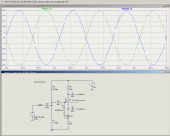
I wasn't familiar with the 2N5551, so I looked up the data sheet. VCEO max is only 160 volts, which isn't enough for most valve circuits....2n5551 delivering an easy 50v p-p at 3ma each side.
To get 50 V p-p at each output, you must have been running the transistor at over 100 volts, but presumably well below 160 to have some safety margin.
I've used the little LND150 N-channel depletion mode MOSFET as a source-o-dyne. It's available in a TO-92 package (and also in a couple of surface-mount packages), and is rated for up to 500 volts, so it works in the majority of valve guitar amps, except for a handful of exotic, very high power, very high B+ designs.
Power dissipation of the small TO-92 package is limited, and something to be kept in mind when designing this kind of thing. With 300 volts B+ and 1 mA of drain current, optimally biased with one-quarter B+ at the gate, quiescent power dissipation is only 150 mW, which is nice and safe.
-Gnobuddy
Attachments

Good point, I have been using B+ supplies no higher then 145v. At this level the 2n5551 only sees full B+ at clipping point. 10k collector and emitter resistors biased at 30 volts yields 85 volts VCE on 2N5551 average. 125 max 20v min at 50v p-p.
I chose these because I had one on hand and it has low capacitances good for 12AX7. LND150 would be a better choice for higher B+ voltages
I chose these because I had one on hand and it has low capacitances good for 12AX7. LND150 would be a better choice for higher B+ voltages
I favor DC coupling N channel enhancement mode MOSFETs to tube anodes. Good bye biasing worries. For wimpy types, like the 12AX7 and EF86, the ZVN0545A is "ideal". For other types, whose load driving ability is greater, I favor the IRFBC20.
Always install a Zener diode between gate and source to protect against potentially destructive start up transients. Remember, the FET turns on "instantaneously", while the tube will take time to start conducting.
Always install a Zener diode between gate and source to protect against potentially destructive start up transients. Remember, the FET turns on "instantaneously", while the tube will take time to start conducting.
That makes perfect sense for a source-follower to buffer a preceding valve gain stage. Good for driving difficult loads (tone stacks, FX sends), etc.I favor DC coupling N channel enhancement mode MOSFETs to tube anodes. Good bye biasing worries.
But DC coupling like that generally won't work for coupling a valve gain stage to a "source-o-dyne" phase splitter. To get maximum output headroom from the source-o-dyne, you need the FET gate at one-quarter B+, and that low a voltage will be hard to achieve at the anode of a preceding valve stage, particularly if it happens to be a 12AX7.
Direct coupling anode to gate might work with a P-channel enchancement MOSFET instead of an N-channel one, though. In that case, you could set the previous valve's anode at three-quarter B+ (rather than one-quarter), and that would be ideal for the subsequent P-channel MOSFET "source-o-dyne".
-Gnobuddy
I wasn't familiar with the 6922, so I looked it up. Very low anode resistance, and the datasheet shows it works quite happily with 75 volts on the anode. Yes, I can see how this triode could be happy direct-coupled to a source-o-dyne!A 6922 section DC coupled to an IRFBC20 "concertina" phase splitter worked well.
I think I may have some of those ZVP0545As in the junk box. I seem to remember searching Mouser or Digikey a while ago, looking for a 500 volt TO-92 P-channel MOSFET, just because I thought they might come in useful for something the LND150 wasn't well suited for.If you want to try DC coupling a 12AX7 section into a P channel enhancement mode MOSFET, use the ZVP0545A, which is complementary to the ZVN0545A. By all means, please report your findings.
If I do try this, I'll try and remember to come back and post in this thread.
That said, the only application for valves that I'm interested in is for guitar amps, and so I may have different design priorities than you do.
The last time I used a source-o-dyne, it was AC coupled, and I inserted a fixed voltage divider between the input to the source-o-dyne and the anode of the preceding valve. The purpose of the attenuator was to increase nonlinearity and "valveyness" of that preceding valve stage, by letting me driving it harder, without the source-o-dyne itself going into clipping. Deliberately increasing nonlinearity would be madness in a Hi-Fi design, but is exactly what we want in a guitar amp.
I was able to do this because I was using output valves (a pair of little 6AK6 pentodes) that only needed about 20 volts peak-to-peak at the control grid to drive them fully.
The interstage attenuation worked very well, making an immediate audible improvement to what guitarists call "clean tone".
In that application, since I wanted signal attenuation between the driving stage and the source-o-dyne anyway, DC coupling the input to the source-o-dyne wouldn't have been advantageous for my purposes.
-Gnobuddy
- Home
- Amplifiers
- Tubes / Valves
- MosFET or other semiconductor substitute for cathodyne?