hi ,
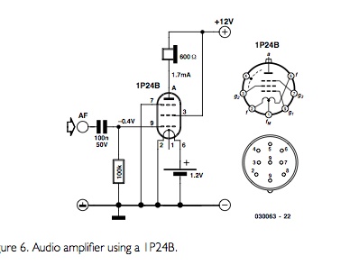
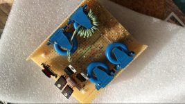
Can any one tell me what is the problem in this circuit. I tried connecting the circuit based on this diagram.I tried making this circuit but its not glowing I did exactly same connections in the picture down but its not lighting . I also used a transformer but still nothing. Do you think the connections of the vacuum is right in the pic. When I connect pin 6 to 1.2V there is a current flows
Can any one tell me what is the problem in this circuit. I tried connecting the circuit based on this diagram.I tried making this circuit but its not glowing I did exactly same connections in the picture down but its not lighting . I also used a transformer but still nothing. Do you think the connections of the vacuum is right in the pic. When I connect pin 6 to 1.2V there is a current flows

An externally hosted image should be here but it was not working when we last tested it.
An externally hosted image should be here but it was not working when we last tested it.
An externally hosted image should be here but it was not working when we last tested it.
An externally hosted image should be here but it was not working when we last tested it.
Last edited:
You only have half of the required filament voltage.
When filaments are series connected, as in you case, the voltage should be 2.4 V.
1.2 V is sufficient when you connect pins 2 and 6 together, and supply the voltage between 1 and 2/6.
Filament current in series connection is some 125 mA and 250 mA in parallel.
When filaments are series connected, as in you case, the voltage should be 2.4 V.
1.2 V is sufficient when you connect pins 2 and 6 together, and supply the voltage between 1 and 2/6.
Filament current in series connection is some 125 mA and 250 mA in parallel.
These little tubes won't glow, even if they are running correctly.
The 60mA filament current is correct for this tube.
thanks for this information
You only have half of the required filament voltage.
When filaments are series connected, as in you case, the voltage should be 2.4 V.
1.2 V is sufficient when you connect pins 2 and 6 together, and supply the voltage between 1 and 2/6.
Filament current in series connection is some 125 mA and 250 mA in parallel.
thanks for this info I tried this I got a current with 190mA which seems better
Since you are using the tube with such low plate voltage, the SPICE model that I made for the tube would not be accurate at all, so you might as well chuck that in the bin.
thank you very much the spice model you made was helpful
but is there any chance you can edit the spice model so it works with 27V
1p24b
The 1p24b is an amazing tube that's capable of tremendous current (for its size) - but you have to treat the filament gently if you want it to last; series 2.4v, parallel 1.2v....180 and 90ma.
I've got a pair running pp on my bench at around 90v and it sounds great! I was just able to turn down B+ to 50v and I can confirm decent sound with less output at that voltage; no other changes... I'm driving with a 1j29b. You can bias the tube through the filament supply by using a dropping resistor on the filament cathode; ie 1.3v battery, 10r resistor... I ended up with about -2v bias for the 1p24b's which seems to be enough for a couple of watts class A.

This one's going to be a guitar amp with an extra 1j29b stage that runs off a battery. Got pretty much all the hum and chugging out of the pwm psu's. It should be small enough to fit into a small hammond box.
Thinking of using the 1p24b pp x2 in a small stereo amp with more volts. It is a nice tube to work with and has nearly zero microphonics!
TM
The 1p24b is an amazing tube that's capable of tremendous current (for its size) - but you have to treat the filament gently if you want it to last; series 2.4v, parallel 1.2v....180 and 90ma.
I've got a pair running pp on my bench at around 90v and it sounds great! I was just able to turn down B+ to 50v and I can confirm decent sound with less output at that voltage; no other changes... I'm driving with a 1j29b. You can bias the tube through the filament supply by using a dropping resistor on the filament cathode; ie 1.3v battery, 10r resistor... I ended up with about -2v bias for the 1p24b's which seems to be enough for a couple of watts class A.
This one's going to be a guitar amp with an extra 1j29b stage that runs off a battery. Got pretty much all the hum and chugging out of the pwm psu's. It should be small enough to fit into a small hammond box.
Thinking of using the 1p24b pp x2 in a small stereo amp with more volts. It is a nice tube to work with and has nearly zero microphonics!
TM

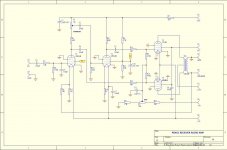
Well I hope you can read this,-a work in progress and I'm still messin with different values. The driver tube is 1j29b which is a nice match. OPT is a PE 4.99 special 70v 10w matching transformer...works better than some more pricey units I've tried - expect premature HF roll off but nothing to write home about. 1p24b is a nice tube to play/learn with since it's relatively low voltage.
TM
mmm, yep...these tubes dont glow, or, should i say, they dont glow in the same way as more "standard' tubes.
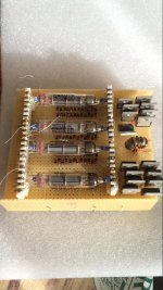
if you hold them in the dark, and peer inside very closely, you will see a dull red glow in there. just dont expect them to light up like el84's...

very hard to get a decent pic but hey! thats both filaments!
it was already mentioned, with your shown schematic, you need 2.4v.
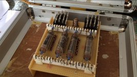
btw... its far easier to work with them if you mount them on veroboard, make little boards you can then plug into a breadboard or solder to. the wires are delicate and dont appreciate too much bending around. once broken (usually right at the glass), a perfectly good tube is to all intents and purposes, a dud.
i had a single 1j24b from an ebay guitar preamp that did exactly that before i got around to veroboarding it.
sure, theyre cheap and readily available, but stocks wont last forever!
ive got 2 1j29b and 2 1p24b setup that way, they all fit my 8-bay breadboard very nicely, perfect for experimenting.

yes, i only have the filaments wired up for photographic reasons.
would you believe ive had that board for several years and this is the first project ive actually USED it for?
if you hold them in the dark, and peer inside very closely, you will see a dull red glow in there. just dont expect them to light up like el84's...
very hard to get a decent pic but hey! thats both filaments!
it was already mentioned, with your shown schematic, you need 2.4v.
btw... its far easier to work with them if you mount them on veroboard, make little boards you can then plug into a breadboard or solder to. the wires are delicate and dont appreciate too much bending around. once broken (usually right at the glass), a perfectly good tube is to all intents and purposes, a dud.
i had a single 1j24b from an ebay guitar preamp that did exactly that before i got around to veroboarding it.
sure, theyre cheap and readily available, but stocks wont last forever!
ive got 2 1j29b and 2 1p24b setup that way, they all fit my 8-bay breadboard very nicely, perfect for experimenting.
yes, i only have the filaments wired up for photographic reasons.
would you believe ive had that board for several years and this is the first project ive actually USED it for?
Last edited:
wow, this is a popular thread, ha ha.
update. blew my first 1p24b. oops. accidently touched a filament with my 12v PSU as i was fiddling around. wee, did it light up! still worked with only 1 filament...but i want full power. so thats one tube down. glad i bought 10.
anyways. wired it up with a fairly standard setup, 500k grid, 10R to G2, 1.2 v across both filaments, taking both f- to ground.
60V supply, 1k:8R OPT (largest ratio thats small enough to plug into the breadboard), and with or without any bias (just another nimh for now, though i did experiment a bit and found values between 1.5k to 3.9k from f- to ground helped) i got quite a nice output when fed with my signal source of 3v. read about 1.5v on the secondary of transformer, and surprisingly loud through a 6ohm speaker.
taking G2 from anode to HT+ kicked volume up a fair amount. as expected.
now im just about to try using another transformer(CT600R:8R, or 3k:3kCT) as phase inverter, i really dont want to have to use yet another filament battery to use a 1j29b as a cathodyne PI. but will also try that. obviously for a PP output on the 1p24b's.
already looks like i will be using at least 4 batteries for this thing as it is... 2 different bias, power supply, filament heating...ARRRGH! but what else will work for a battery powered guitar amp? at least the bias ones dont need replacing too often.
just waiting for my 150V boost converter to arrive. i want an earsplitting 4W output!
alwineden,
Self splitter push pull requires the DHT filaments to be returned through a current source to ground (or at least through a common resistor to ground).
You made the filaments return directly to ground.
The top pentode is doing all the driving of the output transformer.
The bottom pentode is a constant current source, but your circuit is not push pull.
I wouldn't recommend using the pair as a 'self' splitter'. If you use a current source, you will need a floating heater supply. I used this idea in an AGC loop amplifier (where I needed to be able to adjust cathode voltage independent of heater). In any case, common screen currents upset the equation (as the screens draw more current as the anode approaches 0v, but do not drop to zero in the other direction!). I used another pentode for the inverter. Yes, it is ugly, but preferable to using a transformer!
Attachments
Nice project !
And is it working?
I have build a small amp with these as well using a David Berning circuit.
With this i do not need any output transformers as such.
I derived it from the "MicroZotl" schematic.
And is it working?
I have build a small amp with these as well using a David Berning circuit.
With this i do not need any output transformers as such.
I derived it from the "MicroZotl" schematic.
Attachments
i finally got the urge to start playing breadboards again the other day.
another thread and a mention in the valve wizards book about mosfets for cathode followers has me sold on using mosfets for cathodyne/concertina phase inverters. just needed some clarification on biasing a FET to work correctly. its all so easy in hindsight! (cheers, gnobuddy!)
simple, and it works... so. that eliminates the issue of having to have a filament supply for the PI tube elevated to 1/4HT, or use some oddball PI with multiple tubes. i like my super simple cathodynes...
wired up my 1p24b's as push pull, running an OPT that i think worked out to be 3.3K to 8R. or was it 16R? whatever.
i had sound.... nothing great, but i was using rather low divider resistances for the PI, along with a basically "no gain" circuit. a ten you ate? really? still, twas nicely bassy, crisp and clear. even with a torn speaker cone, unbaffled... a good enough result to delve in further, at least.
started on wacking in the 1j29 for the preamp, but then i did something silly and fried my lil 120V boost convertor. (and made that tube light up like a lightbulb!)... so, no more HT. my silicon chip 250V boost convertor got scared watching the smoke escape from its buddy and decided to stop working sometime between testing it the night before and actually setting it up to use... terrible design anyway!( like the tube preamp it came attached to...)
now im just contemplating making a boost convertor with multiple outputs...250V, 150V, 75V and 1.2 or 2.4 v, all isolated so earthing isnt such a big challenge.
or just give up and settle on using standard tubes... indirectly heated cathodes running on a fixed 12V supply are so much more user friendly! only one output on the boost circuit to think about as well...
one good thing about using simple low wattage boost circuits for the HT? you can poke them with bare fingers... first tube amp i ever wired up on a damn breadboard! that might have to change if i really try to drive these lil things... damn it. safety. pffft. who wants to think about safety?
Last edited:
Nice project !
And is it working?
I have build a small amp with these as well using a David Berning circuit.
With this i do not need any output transformers as such.
I derived it from the "MicroZotl" schematic.
not bad... is that some ceramic tagboard filched from a techtronix scope i see there? arent you meant to use silver solder on them?
- Status
- This old topic is closed. If you want to reopen this topic, contact a moderator using the "Report Post" button.
- Home
- Amplifiers
- Tubes / Valves
- 1P24B Russian tube