I tried this circuit and it sounds incredible, far better than the one I tried to cook up. This is very similar to every one I've seen here. They use a type of paraphase with opamps. It works well because the opamp is so fast there is almost no delay. Right now I'm getting a sound that's somewhere between tube LTP and a split load. It's warmer but cleaner than a tube split load phase inverter. Sounds alot like a tube LTP but with less distortion. It's really weird how well this works, doesn't sound like there's an IC stuck in the circuit. I guess it makes sense, professional audio has been splitting phase like this for a long time. All those XLR ins and outs, they don't use signal transformers, they use opamps, maybe hundreds of them.
The schematic I used, disregard the output tubes in the schematic here.
TL082, 12AU7, 2x EL84
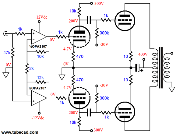
The schematic I used, disregard the output tubes in the schematic here.
TL082, 12AU7, 2x EL84
I tried this circuit and it sounds incredible, far better than the one I tried to cook up.
That's an instrumentation amplifier input stage, not a paraphase.
An oldie but a goodie from Radford, 1979.
http://www.radfordrevival.co.uk/literature/tt100/
http://www.radfordrevival.co.uk/wor...s/2011/11/TT100-Technical-Instructions-P2.jpg
Last edited:
That's an instrumentation amplifier input stage, not a paraphase.
An oldie but a goodie from Radford, 1979.
TT100 | Radford Revival
http://www.radfordrevival.co.uk/wor...s/2011/11/TT100-Technical-Instructions-P2.jpg
You're right, it is indeed an instrumentation amp. Can't believe I missed that.
Interesting, 2 opamp input stages with a transistor LTP. Not sure why they went with transistor drivers. Large voltage swings are not a transistor's strong suit. They certainly have more than enough current to overcome the tiny capacitance of the KT88 grids though. Must be a fast, clean sounding amp with very high damping factor, for tubes.
Last edited:
If you're running EL84 finals in pentode mode with about 300V from cathode to anode and cathode bias around 11~12V, then it seems a bit silly to include the tube driver stage. You could drive the EL84 grids directly from the op-amps, which kicks multiple problems in the butt simultaneously. Op-amp gain should be increased to about 12~15 if you do this --- more if you add feedback. Op-amp power rails should be 15V or a bit more if possible. Some op-amps can handle up to 40V total.
If you're running EL84 finals in pentode mode with about 300V from cathode to anode and cathode bias around 11~12V, then it seems a bit silly to include the tube driver stage. You could drive the EL84 grids directly from the op-amps, which kicks multiple problems in the butt simultaneously. Op-amp gain should be increased to about 12~15 if you do this --- more if you add feedback. Op-amp power rails should be 15V or a bit more if possible. Some op-amps can handle up to 40V total.
I would have to build another stage for gain. Would this circuit stay linear outputting over 10V? I don't know, but I have to try it, it's too tempting. I bet it would have excellent S/N ratio. I'll try it tomorrow.
I would have to build another stage for gain. Would this circuit stay linear outputting over 10V?
If you need more output swing: http://joebrown.org.uk/images/DualPSU/BootstrappingOpAmps.pdf
If you need more output swing: http://joebrown.org.uk/images/DualPSU/BootstrappingOpAmps.pdf
This is a fine line. I don't want to build a solid state amp with a tube output, but it is tempting to do. Opamps are best with small voltages, tubes do large voltage swings with ease, but have capacitance issues. I think the setup I have now is using each device's strength, but I will try it out. After all, that's what diy is all about.
Also the EL84 might be the easiest to drive power tube in the world.
You can go further than that. See page six of this application note showing how to build an amplifier for electrostatic headphones with an lm4562:
http://www.ti.com/lit/an/snaa046a/snaa046a.pdf
It's not the best stat amp for sure, but it's more ambitious than the Stax SRM-001mk2 I listen to all day at work. Which is based on a TL062.
I would have to build another stage for gain. Would this circuit stay linear outputting over 10V?
No need for another stage. Just rejigger the resistors around the op-amps. Most op-amps stay linear up to about 1~2V from each supply rail. That's why I suggested 15V or higher supply rails -- to be sure that your power tubes run out of gas before the driver does. There's no real harm if the grids go slightly positive on signal peaks in a direct-coupled circuit. Output power simply increases a bit. Cathode bias creeps upward any time the tubes venture out of class A operation and class AB2 operation adds to that problem. Some folks tackle this issue with a huge cathode bypass cap, e.g. 10,000uF. At some point, you might want to rework the bias arrangement for better stability.
Also, something that works well with little tubes like an EL84, is to use LM317s instead of cathode resistors.
I had an old Fisher amp that used 7591s (similar drive and bias requirements to the EL84) that shared a common cathode resistor. I had red-plating issues since it was hard to get four really well-matched tubes.
I removed the common resistor and put four individual LM317s, wired in current-source mode, one for each tube. I bypassed the LM317s with caps so that they are voltage sources at AC (just like you would do with a cathode bias resistor). Now all four tubes automatically bias themselves each time I power up and there are no more DC imbalance issues.
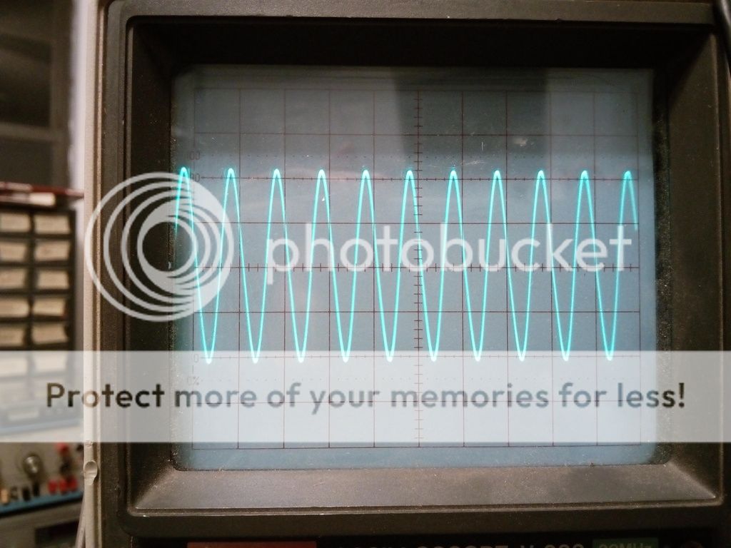
You guys were right about eliminating the 12AU7 stage, it was adding alot of noise, and just sounded odd. I rebuilt it in stereo with a TL084 quad opamp and fixed the noise and ground issues. Now I'm driving the outputs directly from the opamp and it sounds even better. Now it has some real detail and depth to the sound on headphones. I got caught up listening to CD's on it for an hour with no NFB. Still have some difficulties with adding NFB. It doesn't seem to actually change any of the ringing on the scope trace, just lowers the gain, makes the square wave sharper and extends the frequency response flat to 80,000hz, then it fades away quickly at 100,000hz.
Right now there are no capacitors in the circuit, making it a direct coupled amp. I would add them later, don't want a opamp problem to fry my tubes.
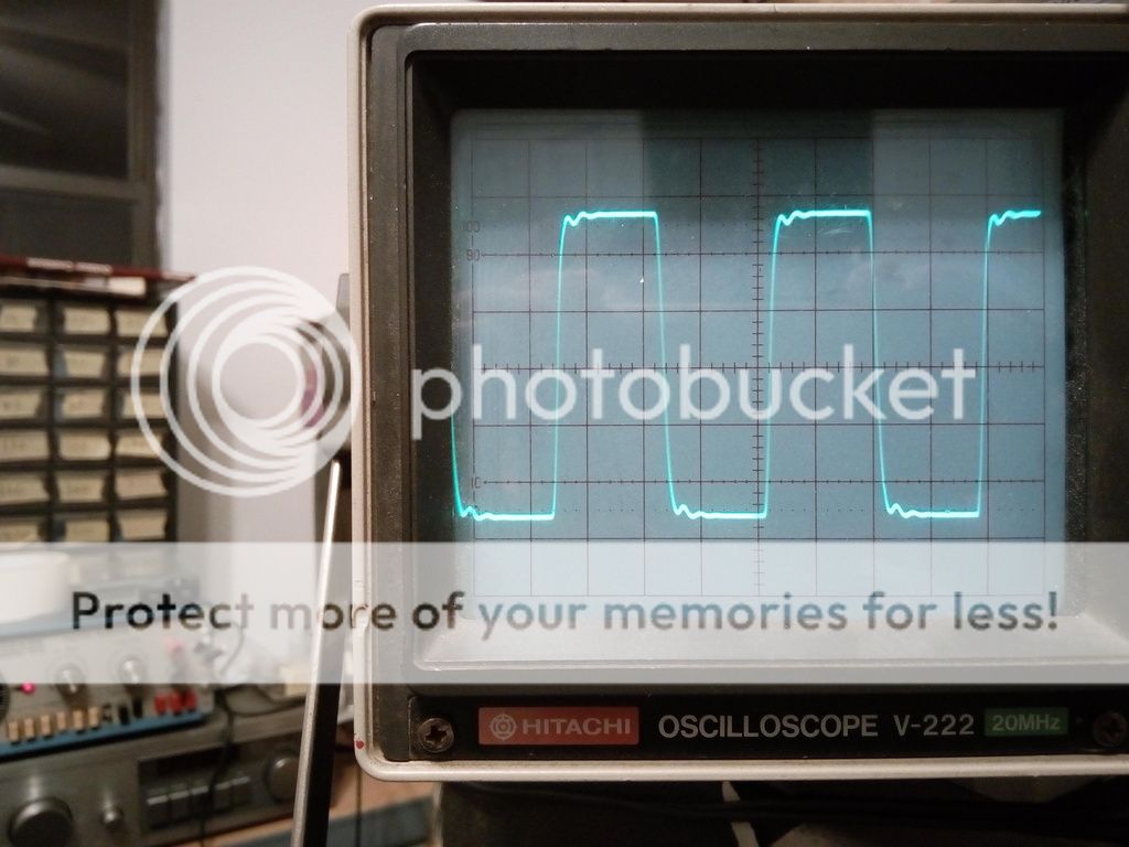
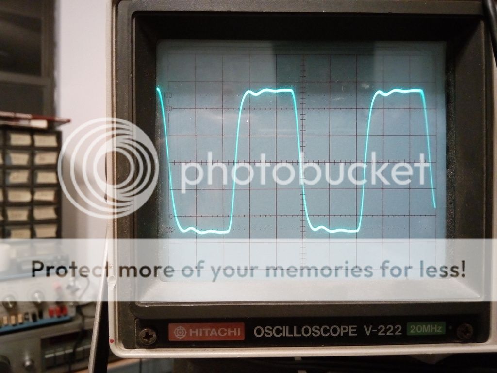
Here are some scope pics without any NFB. Didn't change the gain, just square wave input. The ringing is not from the IC, it must be from the tubes or output transformer.
1k at 1W, no NFB

5k at 1W, no NFB
10k at 1W, no NFB
20k at 1W, no NFB
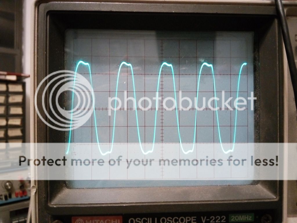
50k at 1W, no NFB
Right now there are no capacitors in the circuit, making it a direct coupled amp. I would add them later, don't want a opamp problem to fry my tubes.
Here are some scope pics without any NFB. Didn't change the gain, just square wave input. The ringing is not from the IC, it must be from the tubes or output transformer.
1k at 1W, no NFB
5k at 1W, no NFB
10k at 1W, no NFB
20k at 1W, no NFB
50k at 1W, no NFB
The ringing is probably an output transformer resonance. It's so mild that you could be forgiven for leaving it be. The usual fix is a snubbing network attached to OPT primary, typically one series RC network across the whole winding, but sometimes more complex.
There's no apparent need for feedback to flatten response at the high end. It's considered mandatory in pentode amps to reduce output impedance, however, and we don't have evidence about low-frequency flatness or distortion yet.
There's no apparent need for feedback to flatten response at the high end. It's considered mandatory in pentode amps to reduce output impedance, however, and we don't have evidence about low-frequency flatness or distortion yet.
The ringing is probably an output transformer resonance. It's so mild that you could be forgiven for leaving it be. The usual fix is a snubbing network attached to OPT primary, typically one series RC network across the whole winding, but sometimes more complex.
There's no apparent need for feedback to flatten response at the high end. It's considered mandatory in pentode amps to reduce output impedance, however, and we don't have evidence about low-frequency flatness or distortion yet.
The resonance is at about 25,000hz. I know about the output impedance, but on headphones it sounds great, but on speakers it would suck. Probably when this thing is done I'll have it switch off the NFB for headphones. It still is odd to look down at the single IC doing it all, preamp and phase inversion. There's so few components there.
What values should I start with for the series RC network?
It's a 5k to 8ohm transformer.
I usually hook up resistor and capacitor substitution boxes across the primary and just tweak for the best squarewave result. Writing in Glass Audio issue 6 of 1995, Jerry Boncer suggested making R equal to end-to-end primary Z and making capacitive reactance equal to R at the ring frequency or a bit lower. That's probably as good a starting point as any.
Correct me if I am wrong but those traces look like they have better phase response than I have seen in most PP amplifiers. Do you have a way to do a phase, IMD and THD graph for this circuit?
Its funny how things have changed in the past few years in tube audio. I proposed something like this a few years ago and got a mixed response. Now it looks like everyone is starting to move to the, "what ever works best is best" camp; and I am glad to see it.
Its funny how things have changed in the past few years in tube audio. I proposed something like this a few years ago and got a mixed response. Now it looks like everyone is starting to move to the, "what ever works best is best" camp; and I am glad to see it.
Now it looks like everyone is starting to move to the, "what ever works best is best" camp; and I am glad to see it.
AMEN! Pragmatism should be in the forefront. I'd use a lump of galena, if it works well. Galena may be OK for an AM envelope detector, but has (IMO) no use in HIFI.
Galena may be OK for an AM envelope detector, but has (IMO) no use in HIFI.
Wait a minute.....can't we distribute "magic" Galena crystals to absorb the evil sound created by the silicon?
")
Its funny how things have changed in the past few years in tube audio.
The early response to PowerDrive (CCS loaded triode driver, mosfet output tube grid drive) was decidedly negative about 10 years ago. I even got some email suggesting my name be changed to Transistorlab. About 400 TSE boards have been sold since then and people seem to like them (PowerDrive and DHT's).
I have some direct coupled hybrid tube / SS amps in the works, including a microprocessor controlled version.....not sure the tube world is quite ready for the Arduino / tube hybrid yet. How about the guitar amp with tubes and an Intel Core I5......That one is being built right now.
Wait a minute.....can't we distribute "magic" Galena crystals to absorb the evil sound created by the silicon?
Do I hear another "AY-men"?
I myself think that tubes are the coolest thing since individually-wrapped cheese slices, but I never did understand the whole purist mentality. The same people who bleat on incessantly about the "evils o' silicon" in a tube amp seem to have no such hangup when it comes to silicon in the signal path of their chosen source - be it a CD player, an iPad, or even a turntable.
I tend to view a well-designed hybrid as a creation that combines the best attributes of both technologies. Like Eli said, whatever works. As for the Arduino/tube hybrid: I say bring it on!
- Status
- This old topic is closed. If you want to reopen this topic, contact a moderator using the "Report Post" button.
- Home
- Amplifiers
- Tubes / Valves
- Has anyone used an opamp to split phase for a tube amp?