I found this one:
Schema_4_KT88PP
Unfortunately my dutch is non-existent...and Google translator is horrible at it too...can you help me to understand what he did here ?
I can understand the ccs at the bottom of the diff.pair. I have that in my Mono-Bill II, too.
But the rest is somewhat new...would love to understand that better...
THX for taking the time.
But the rest is somewhat new...would love to understand that better.
Balanced input stage: The Valve Wizard -Mu Follower
Output stage: two pairs of push pull outputs with current sources, in parallel.
Last edited:
What is so "Ultimate Ultralinear" about it? Just to get attention?

Maybe the amp has sweatbands and face paint

some translating machines do better ...
quote (from dutch site):
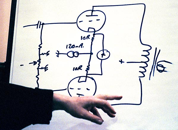
Now the circuit in more detail. To make it myself easy I will start at the output and from there work myself back to the input. The desired power is about 25 watts. This is not all that easy to wring from a Single Ended design. That is why I selected a balanced circuit, in English it's called ' push-pull '. The automatic is negatively here obtained by 'black workers' (aka 'sand' = silicon or transistors) which also improves the symmetry of the circuit because small differences in the tubes are compensated. The two KT88's are connected as ' long tailed pair ' for us peasants known as difference amplifier. So we get a nice symmetrical circuit with good linearity and thanks to the fine tape wound core / split tape core / toroid (?) Schnittbandkern-) transformer a more than adequate bandwidth. The power tubes have to be controlled in anti phase. There are many good phase inverters, but many have the property that the outputs do not have in all respects equal characteristics. This is often considered unimportant, but a real symmetry strikes me as its advantages. So here, too, I opted for a ' long tailed pair ' configuration. In the conventional buildup with a cathode resistor voltage symmetry is only obtained by different values for the anode resistors.
The total current through both tubes is not constant because some of the input voltage on the common cathode resistance falls and this flow so more or less varies depending on the input voltage. Actually not such a perfect situation. The solution is in the constant current source. An infinitely high value for the common cathode resistance is theoretically a good solution however, with some practical disadvantages. A different solution is a current source in place of the cathode resistor. So either a pentode or again some 'sand '. The option with a pentode has the disadvantage that here quite some voltage must fall to work properly and then you run quickly short of supply voltage. With sand this is not the case with the added advantage that a much higher internal resistance is feasible and thus the ideal better approached. Symmetry is for each other.
Only the low output impedance is not yet a fact, that still needs to be worked on. The simplest one is of course to take on anode resistors with low resistance value. Result is that the gain therefore is low and we need to substantially control the phase to provide enough output voltage from KT88's to get to the full. It seems to me that this is not a good plan. We need to solve this otherwise. The first to come to my mind was to build up as mu-stage. A beautiful plan ..... Unfortunately I had to use an extra tube. Another 4 triodes or pentodes. The top tube in a mu-stage is simply used as a current source for the lower tube and cathode follower as seen from the exit of the mu-stage. A triode as a current source is not really a big party so that's not going to be it.
A pentode does all much better, especially as the transconductance increases. But yeah double pentodes are not up for grabs and four additional tube sockets do not fit on the chassis. We need a better solution. Take a few steps back and let the mind run its course. What we need is a current source with a high Ri for the best linearity of the circuit. It should also present a low output resistance. And should have a minimum of tube sockets. A tube without socket with huge gain of a few amperes per volt smells like black magic. And that smell is very real in a power MOSFET. And a minimum of tube sockets, too. The challenge taken and so tried. I don't want to exaggerate but I feel it works perfect, high gain, good linearity and low output impedance.
And all without sockets. In the end that is what went into the amplifier. Then we now have the main features of the amplifier. It consists of a phase shifter and a push-pull output stage. A not mentioned advantage is that you can make the best of course in this configuration of the amplifier from a symmetrical source input. Simply remove the ' ground ' in the triode stage and use it as a second entrance to the balanced pair. I myself do that not because I have no source with balanced output, but for the enthusiast, there is the possibility.
unquote (no guarantee...)
quote (from dutch site):
Now the circuit in more detail. To make it myself easy I will start at the output and from there work myself back to the input. The desired power is about 25 watts. This is not all that easy to wring from a Single Ended design. That is why I selected a balanced circuit, in English it's called ' push-pull '. The automatic is negatively here obtained by 'black workers' (aka 'sand' = silicon or transistors) which also improves the symmetry of the circuit because small differences in the tubes are compensated. The two KT88's are connected as ' long tailed pair ' for us peasants known as difference amplifier. So we get a nice symmetrical circuit with good linearity and thanks to the fine tape wound core / split tape core / toroid (?) Schnittbandkern-) transformer a more than adequate bandwidth. The power tubes have to be controlled in anti phase. There are many good phase inverters, but many have the property that the outputs do not have in all respects equal characteristics. This is often considered unimportant, but a real symmetry strikes me as its advantages. So here, too, I opted for a ' long tailed pair ' configuration. In the conventional buildup with a cathode resistor voltage symmetry is only obtained by different values for the anode resistors.
The total current through both tubes is not constant because some of the input voltage on the common cathode resistance falls and this flow so more or less varies depending on the input voltage. Actually not such a perfect situation. The solution is in the constant current source. An infinitely high value for the common cathode resistance is theoretically a good solution however, with some practical disadvantages. A different solution is a current source in place of the cathode resistor. So either a pentode or again some 'sand '. The option with a pentode has the disadvantage that here quite some voltage must fall to work properly and then you run quickly short of supply voltage. With sand this is not the case with the added advantage that a much higher internal resistance is feasible and thus the ideal better approached. Symmetry is for each other.
Only the low output impedance is not yet a fact, that still needs to be worked on. The simplest one is of course to take on anode resistors with low resistance value. Result is that the gain therefore is low and we need to substantially control the phase to provide enough output voltage from KT88's to get to the full. It seems to me that this is not a good plan. We need to solve this otherwise. The first to come to my mind was to build up as mu-stage. A beautiful plan ..... Unfortunately I had to use an extra tube. Another 4 triodes or pentodes. The top tube in a mu-stage is simply used as a current source for the lower tube and cathode follower as seen from the exit of the mu-stage. A triode as a current source is not really a big party so that's not going to be it.
A pentode does all much better, especially as the transconductance increases. But yeah double pentodes are not up for grabs and four additional tube sockets do not fit on the chassis. We need a better solution. Take a few steps back and let the mind run its course. What we need is a current source with a high Ri for the best linearity of the circuit. It should also present a low output resistance. And should have a minimum of tube sockets. A tube without socket with huge gain of a few amperes per volt smells like black magic. And that smell is very real in a power MOSFET. And a minimum of tube sockets, too. The challenge taken and so tried. I don't want to exaggerate but I feel it works perfect, high gain, good linearity and low output impedance.
And all without sockets. In the end that is what went into the amplifier. Then we now have the main features of the amplifier. It consists of a phase shifter and a push-pull output stage. A not mentioned advantage is that you can make the best of course in this configuration of the amplifier from a symmetrical source input. Simply remove the ' ground ' in the triode stage and use it as a second entrance to the balanced pair. I myself do that not because I have no source with balanced output, but for the enthusiast, there is the possibility.
unquote (no guarantee...)
Last edited:
Looks like some plate to screen feedback too? Tc = 2.2us ?
R3-C1 and R4-C2?
Yes, some feedback, but actually phase correction networks effective round about the self-resonant h.f. of the OPT-tube combination. Although why required here mystifies; I notice no NFB causing such networks to be necessary. (They tailor phase shift round about the mentioned frequency.)
... and with which remark I echo Jazbo8's commentary.
By the way...if Igot it right, than the current source on the cathodes of the powertubes are the "magic Box" Allen Wright was talking about: http://www.vacuumstate.com/fileupload/dpa300B_brochure_lo_rez.pdf
Correct ?
Ok, I should not have titled this thread "ultimate...." but "magic...."
Correct ?
Ok, I should not have titled this thread "ultimate...." but "magic...."
Putting a current source under P-P output tubes forces them to operate in class A mode (unless there is a big bypass cap).
The CCS tail also causes odd harmonic distortion. There is an optimum tail impedance to eliminate odd harmonic distortion, more like 1/gm range. If the tubes are operating around 2.0 power law (typical by the way), then the optimum tail impedance is zero.
The CCS tail also causes odd harmonic distortion. There is an optimum tail impedance to eliminate odd harmonic distortion, more like 1/gm range. If the tubes are operating around 2.0 power law (typical by the way), then the optimum tail impedance is zero.
Hmmm...I was asking myself as well, how Can it be that a current source alone can distribute the current in the right way. What I mean: The target is that both tubes always have the exact same curent flow through the core, so no saturation what so ever. This would reduce distortion as shown by Menno van der Veen in his autobias article.
But the ccs only has one source for both cathodes in this setup. So, as the cathodes are both connected together to the same ccs...would this not have the effect: due to thermal runaways / fluctuations of one tube conducting more that the other tube gets less current ? As the ccs holds the sume of current of both tubes always the same ? So, it would not help to solve the issue, but make it worse ?
Maybe my thinking is twisted
Or is it the opposite: The current is set for both tubes and as long as both want more current set by the negative grid voltage than the ccs delivers, they are both getting the exact same amount of current ? So, how exactly needs negative bias and the ccs work hand in hand to make this happen ?
Menno has his autobias module, which works great when its working. I have three burned out ones by now as the new svetlana sec el34 seem to have quality issues or the grid resistor of 220k is simply too high (Menno's design)....i went away from his modules and have now a classical neg bias setup. But if this ccs achieves the current baalancing game in a safe way, that would be great.
Last edited:
A single, shared CCS cannot balance the average DC currents in the two tubes, only the AC currents. Balance of the DC currents relies on the inherent matching of the two tubes (or lack thereof).how can it be that a current source alone can distribute the current in the right way. What I mean: The target is that both tubes always have the exact same curent flow through the core, so no saturation what so ever.
To match the DC currents accurately, whatever the tube matching, you would need one CCS for each tube, or a DC servo for each tube (e.g. Menno), or some form of cross-coupled topology.
Well, that is the input stage topology I personally consider the ultimate; gyrator plate loads and CCS tail, with a good linear triode. Lowest distortion.
I don't know about the ultralinear output stage with no NFB. It will produce a lot of power, but not the ultimate in linearity by any stretch.
For the ultimate, I'd add source followers to drive the output grids.
I don't know about the ultralinear output stage with no NFB. It will produce a lot of power, but not the ultimate in linearity by any stretch.
For the ultimate, I'd add source followers to drive the output grids.
I was googling around tonight a bit more and found this little article from John B.:
Cathode Bias with a Counstant Current Source
...so...the ccs in the outputstage is giving us ultimate PSRR and CMRR...exactly what Allen was up for...now, two CCS would give us even better the autobias I was hoping for...not implemented in this design...anyone aware of a design where it has been done ? John B. showed a conceptual design in his article...
... two CCS would give us even better the autobias I was hoping for...not implemented in this design...anyone aware of a design where it has been done ? ...
Shoog: http://www.diyaudio.com/forums/tubes-valves/149674-my-version-simple-el84-rise-anti-triode-2.html
And did you sed one per each output tube like shown in John's article ? I love the idea of the autobias ... how does the ccs work together with the neg grid voltage of the tube ? normally the neg. grid voltage determies the current going through the tune, but now the ccs does it as well ?
Ok...found more:
I'm not sure why Allen shows a (-) sign on the fixed grid supply - Allen Wright - Tube DIY Asylum
...where Allen described that the negative bias setting ontop of the ccs helps to rellief the ccs from heat...
...and here the comments of Lynn Olson on this design and his interpretation
http://www.nutshellhifi.com/VSAC2003.html
Ok....that helped me a lot in understanding it better...
Basically, the ccs acts like a cathode resistor and will generate a voltage which will vary across it like in an auto-bias cathode-resistor setting....OK.
maybe I am still a bit slow and stupid here, but I still try to nail the autobias in this here.
Last edited:
cant edit it any more after 30 min...so in addition:
Again, Allen's claim:
"This Magic Box ensures that the total current flowing through the two valves (and the output transformer) is ABSOLUTELY CONSTANT—if one valve’s current goes up just one microamp from (say) 60.000 milliamps (mA) to 60.001mA, then the other one will come down by exactly the same amount, from 60.000 to 59.999mA. This completely solves the microdynamic losses in a conventional P-P amp where these currents are not in any way precisely controlled, and hence allow/cause the cancellation of subtle but vital musical information within the output transformer itself."
Hmmm...I guess I do not really understand why it is good that one valve should go down in current when the other goes up ? That would be good for a SE amp, maybe...but PP ? I would have thought that we want them always to stay at the exact same current ? ...but I guess that is only true if they are not a diff pair ? I am lost.
I trust that Allen knew exactly what he was talking about...I just dont get it.
I would have thought with the analogy of the cathode resistor autobias and the ccs, that the ccs will simply vary the perceived grid voltage to achieve a constant current....ok, it does this now for both tubes together...so, Allen' description should be right as the CCS will force both tubes to always consumes only one total, constant amount of current...so, if one goes up in current, the other goes down.
But why do we want this in a PP ? I would have thought that if one would go up (instead of staying constant), the other should as well, so that the core of the transformer always has symetrical current conditions ? It does not matter for the OPT if I bias the amp with 60mA or 61 or 62 ma....but it matters if both tubes are out of sync and one has 55mA and the other 65 MA which the CCS will force them to ?
Last edited:
- Status
- This old topic is closed. If you want to reopen this topic, contact a moderator using the "Report Post" button.
- Home
- Amplifiers
- Tubes / Valves
- Ultimate Ultralinear Amp...please help to understand...