Just finished my #27 line stage and ready for the next step. It's either continue with the abandoned 6C33C OTL or try a screen drive amp since i just got my 12BQ6GTs, 12V heater version of 6BQ6GT. This thread is to lay out the design process with the hope that someone will catch any mistake before i go to far. I have finished several tube-related projects such as 6FD7 Class AB amp, 6LR8 SE amp, Aikido line stage and Futterman OTL headphone amp so while i am still a beginner in the world of tubes, i know enough how not to kill myself.
Target is 40 to 50 Watt @ 8 ohm per channel. I had an 8W hybrid amp in my room and it's plenty loud so even 30W is more than i should need.
Some design constraints
1. HT of 300VDC for the output stage (from 220V isolation transformer, solid state-rectified and accounting for some drop from RC/LC filtering)
2. Input and drive stage should use the same 300VDC is possible
3. 1 pair of 12BQ6GT per channel
4. OPT is a 50VA mains toroid with 110V+110V primary and 9V-12V-15V-18V-24V secondary. This is what i have and i would like to use it.
5. Full power should be obtained with 1Vpeak input.
Step 1 - Determine the output stage bias point
I will be powering the heaters using a cheap computer PSU. It has +/-12V and +5V. The plan is to power the heaters using the +12V and use the -12V to bias for the output stage: a combination of -12V fixed bias and a bypassed LM317 CCS cathode bias to take care of the remaining Vgk needed. I could of course use that PSU to make -24V negative bias to gain more Vak (less cathode bias) but since toroid OPTs need good plate current balance to avoid saturation, i thought CCS is a good way to achieve this and -12V fixed bias will spare enough headroom for the LM317 to work.
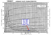
Now, what is the target plate dissipation, Pdiss? 6BQ6GT is rated for max 11W Pdiss. I read that this is rather conservative and we can actually run it a bit hotter but i would like to stay within specs. I'll choose the usual 70% of max Pdiss which is 70% x 11W = 7.7W. Assuming Vak = 300V, this means Ia of 7.7/300 = 25mA. The actual Vak will be lower since i'm using mixed bias and end up with even lower Pdiss. This will be clear on the next paragraph.
I will use the available plate characteristic curve with Vg2 = 150V to keep guessing to a minimum. At around Vak = 300V, to achieve 25mA of plate current, we need Vgk of -30V. With -12V fixed bias, this leaves -18V of cathode bias. This is also the working voltage of the LM317 and it's safely within the maximum 37V rating. So.. the actual Vak will be 300V - 18V = 282V. Actual Pdiss is 282V * 25mA = 7W. The LM317 will dissipate 18V * 25mA = 0.45W which is small enough to skip using heatsink
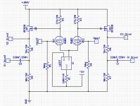
Attached is the output stage bias point. At this point, it should be obvious that i won't be using pure G2 screen drive. Instead i will also drive G1 grid. This should help to reduce the G2 drive requirement. For the next step i will venture into the loadlines. Again, if anyone catches any mistake, please comment. 6BQ6 Screen Drive amp schematic will also help.
Question: i read some screen drive runs at very low plate current, some even 3mA.. and that is with G1 tied to cathode (Vgk=0). So i imagine Vg2 will be quite low (rough guess 25-50V, depending on the tube). First question is WHY such low current? Won't this mean crazy drive requirement for the G2? This is also very close to class B.. How do they cope with the crossover distortion?
Target is 40 to 50 Watt @ 8 ohm per channel. I had an 8W hybrid amp in my room and it's plenty loud so even 30W is more than i should need.
Some design constraints
1. HT of 300VDC for the output stage (from 220V isolation transformer, solid state-rectified and accounting for some drop from RC/LC filtering)
2. Input and drive stage should use the same 300VDC is possible
3. 1 pair of 12BQ6GT per channel
4. OPT is a 50VA mains toroid with 110V+110V primary and 9V-12V-15V-18V-24V secondary. This is what i have and i would like to use it.
5. Full power should be obtained with 1Vpeak input.
Step 1 - Determine the output stage bias point
I will be powering the heaters using a cheap computer PSU. It has +/-12V and +5V. The plan is to power the heaters using the +12V and use the -12V to bias for the output stage: a combination of -12V fixed bias and a bypassed LM317 CCS cathode bias to take care of the remaining Vgk needed. I could of course use that PSU to make -24V negative bias to gain more Vak (less cathode bias) but since toroid OPTs need good plate current balance to avoid saturation, i thought CCS is a good way to achieve this and -12V fixed bias will spare enough headroom for the LM317 to work.
Now, what is the target plate dissipation, Pdiss? 6BQ6GT is rated for max 11W Pdiss. I read that this is rather conservative and we can actually run it a bit hotter but i would like to stay within specs. I'll choose the usual 70% of max Pdiss which is 70% x 11W = 7.7W. Assuming Vak = 300V, this means Ia of 7.7/300 = 25mA. The actual Vak will be lower since i'm using mixed bias and end up with even lower Pdiss. This will be clear on the next paragraph.
I will use the available plate characteristic curve with Vg2 = 150V to keep guessing to a minimum. At around Vak = 300V, to achieve 25mA of plate current, we need Vgk of -30V. With -12V fixed bias, this leaves -18V of cathode bias. This is also the working voltage of the LM317 and it's safely within the maximum 37V rating. So.. the actual Vak will be 300V - 18V = 282V. Actual Pdiss is 282V * 25mA = 7W. The LM317 will dissipate 18V * 25mA = 0.45W which is small enough to skip using heatsink
Attached is the output stage bias point. At this point, it should be obvious that i won't be using pure G2 screen drive. Instead i will also drive G1 grid. This should help to reduce the G2 drive requirement. For the next step i will venture into the loadlines. Again, if anyone catches any mistake, please comment. 6BQ6 Screen Drive amp schematic will also help.
Question: i read some screen drive runs at very low plate current, some even 3mA.. and that is with G1 tied to cathode (Vgk=0). So i imagine Vg2 will be quite low (rough guess 25-50V, depending on the tube). First question is WHY such low current? Won't this mean crazy drive requirement for the G2? This is also very close to class B.. How do they cope with the crossover distortion?
Attachments
Last edited:
JFirst question is WHY such low current? Won't this mean crazy drive requirement for the G2? This is also very close to class B.. How do they cope with the crossover distortion?
With a high perveance tube (NOT 6BG6), you can get away with very low idle and the linearity doesn't suffer- it's analogous to a zero bias triode. The linearity at those low currents is quite good and there's really no significant crossover distortion (look at the curves for a sweep tube with Vg1k = 0 and different Vg2k). And you can help this along by running at high plate voltages- 300V is much too low. I don't know if that the case for a "hybrid" g1g2 drive and a low perveance tube.
The driver stage will indeed be critical- the tradeoff in screen drive is the need for lots of swing!
One other hint: in my successful screen drive amps, there's a significant amount of feedback from the plate of the output tubes back to the driver.
Hi SY,
Do you mind explaining simply what is perveance? Or point a link which explains it. Is it how sensitive the change of plate current VS change of Vg2k? 6CU6 is said to be high perveance (it says so here http://www.nj7p.org/Tubes/PDFs/Frank/093-GE/6CU6.pdf) but i can't find any difference between it and the 6BQ6GT i am using.. i'll even say they're exact equivalent. Did you misread my tube as 6BG6?
Step 2 - Choosing OPT Primary Impedance and Loadline
This amp will certainly be Class AB so the max output power will be determined by the Class B loadline. During the class B part, each 12BQ6GT handles 1/4 of the OPT Zaa primary impedance. With the mains toroid OPT i have, these are the Zaa calculations:
The 9V secondary has 220V/9V = 24.4 winding ratio. With 8 ohm speaker connected, the reflected impedance on the primary or Zaa is 24.4^2 * 8 = 4700 ohm. 1/4 of that is 1200 ohm. Here's the Zaa of the remaining secondaries.
9V has Zaa 4700R
12V has Zaa 2700R
15V has Zaa 1700R
18V has 1200R
24V has 670R
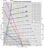
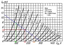
Attached is the Class B loadlines for each secondary tap plotted on plate characteristic with various Vg2k values and Vg1k = 0. This is one possible mistake i could make: i assume i can simply extrapolate for the missing Vg2k by estimating the position relative to the previous Vg2k curves? Vg2k 225V to 275V is obviously my attempt to extrapolate. Are they reasonable?
Blue is for 9V secondary load line. Plate current at Vak=0 is obtained by dividing Vak (282V) with 1/4 Zaa (1200R) which is 235mA. The loadline then is drawn from Ia=0mA@Vak=282V to Ia=235mA@Vak=0V.
12V is green.. 15V is red.. 18V is purple and 24V is yellow.
I can then calculate the max output power for each loadline. I have done so and found that the 15V secondary with Zaa 1700R yields the target Power Output while maintaining G2 swing to a minimum. Let's see if i make the correct calculation..
Peak voltage swing will be around 282V - 80V = 182V. 80V being the Vak value where the red loadline goes through the Vg2k=225V knee and enter saturation area. At the same point, we reach Ia = 475mA. This means my max power output will be (182V * 475mA) / 2 = 43W. This is on the primary side.. assuming OPT efficiency of 85% (is this reasonable?), i get 36W at the speakers.. so slightly lower than my target but i can live with that.
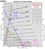
Having chosen the 15V tap as the speaker output, I can then finally draw the Class AB loadline. 2nd attached picture is the result. As it can be seen, there isn't much "Class A" on this amp.
Having finished Step 1 and Step 2, I can then draw these three conclusions, which will subsequently be the driver stage requirements.
1. At idle, Vg2k is 150V and Vg1k is -30V
2. At the max swing, Vg2k is 225V and Vg1k is 0V
3. G2 will swing 225-150 = 75Vpeak and G1 will swing 30-0=30Vpeak.
I will next layout the driver stage design and hopefully i can get by with whatever tube i have in my stash.
Final attached pic is the output stage design.. While drawing the OPS, i realized one minor mistake. I forgot to account for the OPT primary resistance.. This will reduce Vak even further and, subsequently max power output but I did use 85% OPT efficiency, in reality i might get higher efficiency since i'm using toroidal OPT.. so i guess i'm still not far off from my target.
50R resistor under the LM317 is calculated to achieve 25mA idle current which is from 1.25V/25mA. 470K grid leak resistor merely follows the max allowed value from the spec sheet. I do need help on the bypass capacitor..
1. I chose 1000uF by simple calculation of assuming the LM317 replaced by a resistor of 720R (from 18V cathode bias and 25mA idle current) and choose the cap value to yield less than 1Hz cutoff freq. Is this reasonable?
2. Is there any advantage if i choose to connect the bypass cap as shown on the anti-triode circuit on post #11 here: http://www.diyaudio.com/forums/tubes-valves/149674-my-version-simple-el84-rise-anti-triode-2.html .. I imagine since i have a heavy Class B part, there should be a way to prevent the bypass caps from charging up and mess with the bias voltage?
edit: another mistake.. G2 should be biased to 18V + 150V = 168V to maintain Vg2k = 150V as the the cathode sits 18V above ground.
Do you mind explaining simply what is perveance? Or point a link which explains it. Is it how sensitive the change of plate current VS change of Vg2k? 6CU6 is said to be high perveance (it says so here http://www.nj7p.org/Tubes/PDFs/Frank/093-GE/6CU6.pdf) but i can't find any difference between it and the 6BQ6GT i am using.. i'll even say they're exact equivalent. Did you misread my tube as 6BG6?
Step 2 - Choosing OPT Primary Impedance and Loadline
This amp will certainly be Class AB so the max output power will be determined by the Class B loadline. During the class B part, each 12BQ6GT handles 1/4 of the OPT Zaa primary impedance. With the mains toroid OPT i have, these are the Zaa calculations:
The 9V secondary has 220V/9V = 24.4 winding ratio. With 8 ohm speaker connected, the reflected impedance on the primary or Zaa is 24.4^2 * 8 = 4700 ohm. 1/4 of that is 1200 ohm. Here's the Zaa of the remaining secondaries.
9V has Zaa 4700R
12V has Zaa 2700R
15V has Zaa 1700R
18V has 1200R
24V has 670R
Attached is the Class B loadlines for each secondary tap plotted on plate characteristic with various Vg2k values and Vg1k = 0. This is one possible mistake i could make: i assume i can simply extrapolate for the missing Vg2k by estimating the position relative to the previous Vg2k curves? Vg2k 225V to 275V is obviously my attempt to extrapolate. Are they reasonable?
Blue is for 9V secondary load line. Plate current at Vak=0 is obtained by dividing Vak (282V) with 1/4 Zaa (1200R) which is 235mA. The loadline then is drawn from Ia=0mA@Vak=282V to Ia=235mA@Vak=0V.
12V is green.. 15V is red.. 18V is purple and 24V is yellow.
I can then calculate the max output power for each loadline. I have done so and found that the 15V secondary with Zaa 1700R yields the target Power Output while maintaining G2 swing to a minimum. Let's see if i make the correct calculation..
Peak voltage swing will be around 282V - 80V = 182V. 80V being the Vak value where the red loadline goes through the Vg2k=225V knee and enter saturation area. At the same point, we reach Ia = 475mA. This means my max power output will be (182V * 475mA) / 2 = 43W. This is on the primary side.. assuming OPT efficiency of 85% (is this reasonable?), i get 36W at the speakers.. so slightly lower than my target but i can live with that.
Having chosen the 15V tap as the speaker output, I can then finally draw the Class AB loadline. 2nd attached picture is the result. As it can be seen, there isn't much "Class A" on this amp.
Having finished Step 1 and Step 2, I can then draw these three conclusions, which will subsequently be the driver stage requirements.
1. At idle, Vg2k is 150V and Vg1k is -30V
2. At the max swing, Vg2k is 225V and Vg1k is 0V
3. G2 will swing 225-150 = 75Vpeak and G1 will swing 30-0=30Vpeak.
I will next layout the driver stage design and hopefully i can get by with whatever tube i have in my stash.
Final attached pic is the output stage design.. While drawing the OPS, i realized one minor mistake. I forgot to account for the OPT primary resistance.. This will reduce Vak even further and, subsequently max power output but I did use 85% OPT efficiency, in reality i might get higher efficiency since i'm using toroidal OPT.. so i guess i'm still not far off from my target.
50R resistor under the LM317 is calculated to achieve 25mA idle current which is from 1.25V/25mA. 470K grid leak resistor merely follows the max allowed value from the spec sheet. I do need help on the bypass capacitor..
1. I chose 1000uF by simple calculation of assuming the LM317 replaced by a resistor of 720R (from 18V cathode bias and 25mA idle current) and choose the cap value to yield less than 1Hz cutoff freq. Is this reasonable?
2. Is there any advantage if i choose to connect the bypass cap as shown on the anti-triode circuit on post #11 here: http://www.diyaudio.com/forums/tubes-valves/149674-my-version-simple-el84-rise-anti-triode-2.html .. I imagine since i have a heavy Class B part, there should be a way to prevent the bypass caps from charging up and mess with the bias voltage?
edit: another mistake.. G2 should be biased to 18V + 150V = 168V to maintain Vg2k = 150V as the the cathode sits 18V above ground.
Attachments
Last edited:
I think one mistake you are making here is to assume that your output transformer is going to be 8 ohms on the secondary just because you attach an 8 ohm speaker. Since you are using a power transformer as an OPT how are you calculating its impedances on the secondary? It won't be the same as an audio transformer. You are assuming the load creates the impedance of the winding. It ( the true reflected impedance) could be 1/2 ohm or 40 ohms ... on the 9v output.
Last edited:
While there isn't a huge difference, the screen drive and the "crazy drive" (g1 and g2 driven) will have a different Ep-Ip characteristic than the plain g1 drive. Perhaps you can ask smoking-amp to trace a 12BQ6 for you (assuming he has the tube). It probably will not make a big difference for the output power, but the result could be quite different for the harmonic distortion.
You're right, I misread the tube number.
Perveance is the coefficient of the triode equation for plate current.
Ip = P(Vg + (Vp/mu))^3/2
With a pure screen drive, you can go a lot higher on the plate voltage, then draw your load line to tuck into the "knee" of the curve. You'll be amazed at how much power you can get if you can work out the drive arrangements. George (tubelab) has taken my early versions (6LF6 with 700V, 3mA idle current, and low plate-plate load) and done some amazing variations, extracting huge amounts of power from small tubes.
Here are some 12BQ6 curves for g2 drive and "Crazy Drive" (hybrid g2 and g1).
http://www.diyaudio.com/forums/tube...gnificent-television-tubes-2.html#post4578292
When the datasheet refers to high perveance, they are usually talking about the g1 gm being high. For g2, divide that by the g2/g1 Mu factor. So for the 12BQ6GT, gm1 = 5550 at 55 mA, Mu = 4.3, so gm2 = 5550/4.3 = 1290 (about what a 12AX7 has for g1 gm!)
Here are some data for TV Sweeps in general, for g2 drive purposes. This gives the plate knee current available for g2 = 150 V (with g1 = 0 V). Tubes at the top of the list are the more desirable for g2 drive. (For example, a 35LR6 could get you gm2 = 16000/3.5 = 4571)
Crazy Drive (g2 and g1 hybrid) can reduce the drive voltage requirement by around 33% from plain g2 drive. It's also more linear. Same high Rp out though, so some kind of N Fdbk needed to lower output Z.
List of knee currents for g2 = 150 V, g1 = 0 V, Vp = 60 to 80 V
<tube> <Watts> <mA knee@150Vg2> <gm1> <Mu> <maxDCmA> <registered by> <date>
6LF6 40W 1144mA@150V 15K@125mA Mu3 500mADC Amperex 1968
6KG6/EL509 34W 1135mA@150V 13K@150mA Mu3.2 500mADC Amperex 1965
6MC6 33W 1130mA@150V 14K@125mA Mu4 400mADC RCA (6LX6 clone) 1972
13E1 90W(absmax) 1120mA@150V 35K@500mA Mu4.5 800mADC AEI 1961
6MH6 38.3W 1100mA@150V 14K@125mA Mu4 500mADC GE (up-rated 6LX6,6KD6,26HU5) 1972
6MB6 38W 1085mA@150V 14K@110mA Mu3.5 400mADC Sylvania 1971
6LR6 30W 1085mA@150V 16K@140mA Mu3.5 375mADC Sylvania 1968
6LX6/6KD6/26HU5 33W 1080mA@150V 14K@125mA Mu4 400mADC GE 1969/1965/1969
6LW6 40W 1050mA@150V 12K@125mA Mu3.7 400mADC GE 1971
6KN6 30W 1050mA@150V 16K@100mA Mu4.5 400mADC Sylvania 1965 (later versions are 6KD6)
6LZ6 30W 940mA@150V 11K@140mA Mu3 350mADC RCA 1971
6LB6/A 30W/35W 825mA@150V 13.4K@105mA Mu4 315mADC GE 1967
6JE6C/6JS6C 30W 789mA@150V 10.5K@130mA Mu3 350mADC Sylvania 68/69
6JE6 24W 762mA@150V 9.6K@115mA Mu3 315mADC RCA 1962
6JS6/6HF5 28W 749mA@150V 11.5K@130mA Mu3 315mADC GE 1964/1963
6MJ6 30W 740mA@150V 11K@100mA Mu3.6 350mADC RCA 1973
6LG6 28W 740mA@150V 11.5K@90mA Mu3.6 315mADC GE 1967
6LQ6 30W 715mA@150V 7.5K@95mA Mu3 350mADC RCA 1967
6ME6 30W 700mA@150V 9.6@130mA Mu3.5 350mADC RCA 1971
6DQ5 24W 690mA@150V 10.5K@110mA Mu3.3 315mADC RCA 1957
6JF6/6JG6 17W 660mA@150V 10K@80mA Mu4.1 275mADC RCA 1965/1964
6KM6 20W 630mA@150V 9.5K@80mA Mu4 275mADC RCA 1965
6HD5/6HJ5 24W 630mA@150V 10K@80mA Mu4.2 280mADC Raytheon 1962/1963
6JR6/6JU6 17W 600mA@150V 7K@45mA Mu4.7 275mADC RCA 1968/1966
6JZ6/21HB5A 18W 560mA@150V 9K@46mA Mu4.8 230mADC GE 1966/1964
12HE7 10-15W 540mA@150V 8.8K@60mA Mu4.2 200mADC GE (15W if damper disabled) 1964
6CL5 25W 514mA@150V 6.5K@90mA Mu3 240mADC Sylvania 1955
6GB5/29KQ6/EL500 17W 500mA@150V 13K@100mA Mu5.1 275mADC Amperex 1961/Matsushita 1959/Philips 1961?
6KV6/A 20-28W 488/610mA@150V 6K@40mA Mu4 275mADC RCA (re-rated 6KM6?) 1967/1969
6HB5/6GY5/21JV6/6KE6/16KA6 18W 475mA@150V 9.1K@50mA Mu4.7 230mADC GE/GE/GE/Ray/Tung 1962/1962/1965/1965/1964
6EX6 22W 460mA@150V 7.7K@67mA Mu4.2 220mADC Raytheon (up-rated 6CD6) 1959
6CB5/A 23W 440mA@150V 8.8K@90mA Mu3.8 240mADC RCA 1954/1956
6CD6/GA 15/20W 422mA@150V 7.7K@75mA Mu3.9 200mADC RCA/GE 1949/1954
6GT5/6GJ5/6JT6/6JB6/6GW6 17.5W 380mA@150V 7.1K@70mA Mu4.4 175mADC RCA 1961/1961/1964/1962/1961
6GE5 17.5W 350mA@150V 7.3K@65mA Mu4.4 175mADC GE 1961
6GF5 9W 345mA@150V 4.7K@34mA Mu4.2 160mADC GE 1961
6JM6/6JN6/6FW5/6GC6 17.5W 340mA@150V 7.3K@70mA Mu4.4 175mADC GE 1964/1964/1960/1960
6DQ6B/6GV5 17.5W/18W 330mA@150V 7.3K@65mA Mu4.4 175mADC GE 1959/1962
6DQ6/A 18W 280mA@150V 6.6K@55mA Mu4.1 120/155mADC CBS/RCA 1955/1956
6JA5/10JA5 19W 276mA@150V 10.3K@95mA Mu5.5 110mADC GE 1971
6LU8/6LR8//6MY8 14//16W 265mA@150V 9.3K@56mA Mu6.5 75mADC Sylvania 1964/1964//1970(Toshiba)
6AV5/GA///6BQ6/GA 11W 255ma@150V 5.9K@57mA Mu4.3 110mADC CBS/GE 1949/1955 /// CBS/Syl 1949/1953
KT120 60W 221ma@150V 190mADC
KT90 50W 220mA@150V
6Y6G/GT/GA 12.5W 200mA@150V Ray 1937/KenRad 1939/Syl 1954
6550A 35W/42W 190mA@150V 11K@140mA 190mADC
6W6GT 10W 185mA@150V 8K@46mA Mu6.2 65mADC CBS 1939
KT88 35W 170mA@150V 175mADC
6CA7/EL34 25W 107mA@150V 11K@100mA Mu10.5 150mADC Philips 1952
6JC5 19W 80mA@150V 4.1K@43mA Mu7 75mADC Sylvania 1971
6L6/G/GA/GB/GC 30W 77mA@150V 4.7K@40mA Mu8 110mADC RCA 1936/Ray 1936/Syl 1943/Syl 1954/GE 1958
6HB6 10W 70mA@150V 20K@40mA Mu33 60mADC Raytheon 1961
6GK6 13.2W 65mA@150V 11.3K@48mA Mu19 65mADC CBS 1959
6BQ5/EL84 12W 65mA@150V 11.3K@48mA Mu19.5 65mADC Rogers 1956
6V6G/GT 14W 45mA@150V 4.1K@45mA Mu9.8 40mADC KenRad 1936/CBS 1939
Last edited:
Thank you smoking-amp for the curves.. so, hybrid/"crazy" drive seems to be more linear.. at least on the lower Vg2k shown. I do realize some NFB will have to be introduced somewhere.. i'm not sure how to do it yet. It will be a three stage amp so i'm worried about stability if going gNFB.
Yes.. i realize this and i do think it is a problem on the lower frequencies as the inductances are lower than a well-made audio OPT.. It's budget build so i can't do much about it. Most likely this amp will be paired with a Class D powered subwoofer so at least i won't have to worry about reproducing lower notes.
Step 3 - Driver Stage Design
As mentioned above, this will be a budget build so i won't have much to spend on the power supply section. LC filtering is out of the question so i have to design the amp itself to have good PSRR. This translates to LTP stages for input and drive stage. Although the PS have ripples, if we introduce the same ripple on both output tube plates the net result on the OPT secondary is zero. The idea is similar to John Broskie's mod on Bruce Heran's SRPP EL84 PP amp here: PS-15 & SRPP Designs
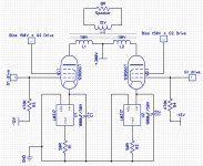
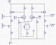
First attached pic is the basic idea for the driver stage. As can be seen, G2 is DC-coupled while G1 is driven from a resistive divider from G2. Some component values are still missing and i will lay out the thought process to get the values, hopefully exposing any logic mistake i have and fix it before it goes too far.
So.. as stated on Step 2, here's the requirement for the driver stage:
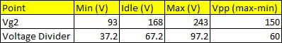
1. G2 should be biased to around 150+18 = 168V and it will swing 150Vpp.. so between 243V and 93V.
2. G1 has -12V fixed bias and will swing 60Vpp.
G2 max and min excursion seem to tuck comfortably within the 300V HT+ so i think i can use the same HT+ for the driver stage AND DC couple to G2.
My MOSFET choice is IRF820.. I realize there are better options with lower Crss out there but i'm not sure if i can get them locally. If anyone can come up with some options, i can try to check before i get the IRF820. Since the MOSFET is also DC-coupled to the driver stage, i need to know what is the target plate voltage. I know that G2 should be biased to 168V above ground.. and Vgs threshold for IRF820 is around 3V.. so the plate should be at 168+3 = 171V.. and it swings between 246V and 96V. Knowing this, i can start to draw the loadline for the LTP driver stage. Since 12BQ6GT is octal, i prefer to use the same base throughput the amp.. On my tube stash, the only octals i have are 6N8S and 6N9S, equivalent to 6SN7 and 6SL7, respectively. I need all the plate current i can muster to combat the MOSFET's capacitance so it seems 6N8S is the way to go.
2nd attached pic is the loadline i came up with. As can be seen, idle current for the LTP driver stage is 4.8mA. Is this enough to drive the IRF820 capacitance? Also, i can also calculate the LM317 current set resistor.. which is 1.25/(4.8mA x 2) = 130R. 9.6mA is a tad lower than my usual preference to run LM317 (i prefer at least 10mA) but this should do. This 130R resistor will most likely swapped to a trimpot so i can tune the LTP plate current and achieve the target Vg2k on the 12BQ6GT. I also have to ensure well matched triodes within the 6N8S as i want to avoid too many trimpots to adjust. By the way, Ra calculation should be 294V/11mA as i need to calculate Vak reduction from Vgk.. but this is minor detail.
The remaining values to determine are the voltage divider from G2 that will drive G1 (R6+R7 and R8+R9. I know G2 will swing 150Vpp and G1 will swing 60Vpp. So that's a ratio of 2.5 between the lower resistor value and total voltage divider resistance (or the upper resistor should be 1.5x of the lower resistor value).. I want enough current to drive the 12BQ6GT miller capacitance (help! how to calculate this?) but i don't want excessive current that i waste heat on the resistors and MOSFET. If i choose 10k for the lower resistor, i can get 15k for the upper one which is a value i can still find on E12 series. On idle, the current through these resistors is 168V/(10k+15k) = 6.7mA. The 10k resistor dissipates 450mW and 15k dissipates 680mW. Both are values i am still comfortable in using 2W types.
At idle, the MOSFET supplies currents for two loads: G2 and the resistive divider. We know the resistive divider consumes 6.7mA. From the datasheet we also know that at Vg2k = 150V and Vg1k = -30V, G2 draws 1mA of current. So that's a total of 7.7mA. The MOSFET will then dissipate (300-168)*7.7mA = 1W. Again a safe number for IRF820's TO220 casing with heatsink.
To ensure that i get the correct swing between G2 and G1 with the 10K+15K voltage divider, the attached table shows the values Vg2 and the voltage divider tap for idle, max and min excursion of G2. As can be seen, it has been confirmed that i am getting the required swing both on G2 and G1.
The remaining values to be determined are the LTP grid leak resistor which i choose to be 1Meg and the LTP to OPS G1 coupling cap.. which i choose as 220nF simply because i still have a couple of WIMA MKPs with that value.. Soo.. final pic is the driver stage design.
As i was filling the part values, i saw some potential problem.. During startup, the MOSFET gate will be latched to HT+.. and so will the OPS G2. Will this be a problem? The same reason is why i choose 250V for the coupling cap rating.. as during startup, there is 132V across this cap. Also, there should be a 12V safety zener between the MOSFET Gate and Source.. and the usual grid-gate stopper resistors are still missing. I will draw them on the finalized complete schematic.. assuming i don't bump into any issue i can't solve.
I think one mistake you are making here is to assume that your output transformer is going to be 8 ohms on the secondary just because you attach an 8 ohm speaker.
Yes.. i realize this and i do think it is a problem on the lower frequencies as the inductances are lower than a well-made audio OPT.. It's budget build so i can't do much about it. Most likely this amp will be paired with a Class D powered subwoofer so at least i won't have to worry about reproducing lower notes.
Step 3 - Driver Stage Design
As mentioned above, this will be a budget build so i won't have much to spend on the power supply section. LC filtering is out of the question so i have to design the amp itself to have good PSRR. This translates to LTP stages for input and drive stage. Although the PS have ripples, if we introduce the same ripple on both output tube plates the net result on the OPT secondary is zero. The idea is similar to John Broskie's mod on Bruce Heran's SRPP EL84 PP amp here: PS-15 & SRPP Designs
First attached pic is the basic idea for the driver stage. As can be seen, G2 is DC-coupled while G1 is driven from a resistive divider from G2. Some component values are still missing and i will lay out the thought process to get the values, hopefully exposing any logic mistake i have and fix it before it goes too far.
So.. as stated on Step 2, here's the requirement for the driver stage:
1. G2 should be biased to around 150+18 = 168V and it will swing 150Vpp.. so between 243V and 93V.
2. G1 has -12V fixed bias and will swing 60Vpp.
G2 max and min excursion seem to tuck comfortably within the 300V HT+ so i think i can use the same HT+ for the driver stage AND DC couple to G2.
My MOSFET choice is IRF820.. I realize there are better options with lower Crss out there but i'm not sure if i can get them locally. If anyone can come up with some options, i can try to check before i get the IRF820. Since the MOSFET is also DC-coupled to the driver stage, i need to know what is the target plate voltage. I know that G2 should be biased to 168V above ground.. and Vgs threshold for IRF820 is around 3V.. so the plate should be at 168+3 = 171V.. and it swings between 246V and 96V. Knowing this, i can start to draw the loadline for the LTP driver stage. Since 12BQ6GT is octal, i prefer to use the same base throughput the amp.. On my tube stash, the only octals i have are 6N8S and 6N9S, equivalent to 6SN7 and 6SL7, respectively. I need all the plate current i can muster to combat the MOSFET's capacitance so it seems 6N8S is the way to go.
2nd attached pic is the loadline i came up with. As can be seen, idle current for the LTP driver stage is 4.8mA. Is this enough to drive the IRF820 capacitance? Also, i can also calculate the LM317 current set resistor.. which is 1.25/(4.8mA x 2) = 130R. 9.6mA is a tad lower than my usual preference to run LM317 (i prefer at least 10mA) but this should do. This 130R resistor will most likely swapped to a trimpot so i can tune the LTP plate current and achieve the target Vg2k on the 12BQ6GT. I also have to ensure well matched triodes within the 6N8S as i want to avoid too many trimpots to adjust. By the way, Ra calculation should be 294V/11mA as i need to calculate Vak reduction from Vgk.. but this is minor detail.
The remaining values to determine are the voltage divider from G2 that will drive G1 (R6+R7 and R8+R9. I know G2 will swing 150Vpp and G1 will swing 60Vpp. So that's a ratio of 2.5 between the lower resistor value and total voltage divider resistance (or the upper resistor should be 1.5x of the lower resistor value).. I want enough current to drive the 12BQ6GT miller capacitance (help! how to calculate this?) but i don't want excessive current that i waste heat on the resistors and MOSFET. If i choose 10k for the lower resistor, i can get 15k for the upper one which is a value i can still find on E12 series. On idle, the current through these resistors is 168V/(10k+15k) = 6.7mA. The 10k resistor dissipates 450mW and 15k dissipates 680mW. Both are values i am still comfortable in using 2W types.
At idle, the MOSFET supplies currents for two loads: G2 and the resistive divider. We know the resistive divider consumes 6.7mA. From the datasheet we also know that at Vg2k = 150V and Vg1k = -30V, G2 draws 1mA of current. So that's a total of 7.7mA. The MOSFET will then dissipate (300-168)*7.7mA = 1W. Again a safe number for IRF820's TO220 casing with heatsink.
To ensure that i get the correct swing between G2 and G1 with the 10K+15K voltage divider, the attached table shows the values Vg2 and the voltage divider tap for idle, max and min excursion of G2. As can be seen, it has been confirmed that i am getting the required swing both on G2 and G1.
The remaining values to be determined are the LTP grid leak resistor which i choose to be 1Meg and the LTP to OPS G1 coupling cap.. which i choose as 220nF simply because i still have a couple of WIMA MKPs with that value.. Soo.. final pic is the driver stage design.
As i was filling the part values, i saw some potential problem.. During startup, the MOSFET gate will be latched to HT+.. and so will the OPS G2. Will this be a problem? The same reason is why i choose 250V for the coupling cap rating.. as during startup, there is 132V across this cap. Also, there should be a 12V safety zener between the MOSFET Gate and Source.. and the usual grid-gate stopper resistors are still missing. I will draw them on the finalized complete schematic.. assuming i don't bump into any issue i can't solve.
Attachments
Yes.. i realize this and i do think it is a problem on the lower frequencies as the inductances are lower than a well-made audio OPT.. It's budget build so i can't do much about it. Most likely this amp will be paired with a Class D powered subwoofer so at least i won't have to worry about reproducing lower notes.
.
The input impedance calculation of your OPT is where your assumption of 8 ohms on the output could be way high if the true output impedance is closer to 1-2 ohms. The numbers for input impedance won't match well with your output tubes if the input Z is only 1/8 or 1/4 of what you thought you have. Power trannies should be designed for their best power transfer at the Hz they are designed to be used for. You need to recalculate the output and input Z based on the power output on the secondary if that is where the W rating is based, and then the voltage tap you want to use. 50W @ 9v. Can you put a 50W, 1.6R dummy load on the tranny and run it without overheating?
I will be using the 15V tap, not the 9V. I fully understand that my "wall of text" posts are skipped by most people. I won't argue that my OPT is sub-optimal but as i said, it's what i have and it cost me nothing. Some people have successfully used toroidal power transformer for OPT and i'm hoping to achieve the same.
http://www.diyaudio.com/forums/tubes-valves/129030-using-mains-transformer-output-transformer.html
Since my OPT is 50Hz rated, with 8 ohm speakers, at least i am expecting 15^2/8=29W at 50Hz.. which is still less than the 50VA rating of my transformer. If i skip on the subwoofer and expect it to reach, say, 25Hz.. i think it's reasonable to half the voltage to 7.5V and expect 7W which is still plenty loud from my experience.
Another approach is to think that the 110V tap is designed to run 50W all day swinging 110*1.414 = 155Vpeak. Well maybe not all day since i'm sure some derating is involved to lower price but then i also won't be listening to 50W all day. Anyway, 155Vpeak.. we can see on the loadline, if we expect the "OPT" to swing the same 155Vpeak from the idle Vak of 282V, it will reach 282-155 = 127V of Vak. This corresponds to around 375mA peak current and, subsequently, 155V*375mA/2 = 29W. Again this is at 50Hz and lower than the 50VA rating.. If i use subwoofer and limit this amp to working above 100Hz, i think it's safe to say that i can reach the 40-50W target.
Please don't take this post as a counter-argument. I already agree that my OPT is sub-optimal with its lower inductance than a well made audio OPT.. but i work with what i have.
Last edited:
I recall that Tubelab posted some results of 6BQ6's with screen drive but I could not locate the schematic (perhaps he never posted it), anyway, it should be a good design to study. I don't think he ever used IRF MOSFET's though, so you may want to look into the reason why he skipped them.
6BQ6 or 6AV5? They're nearly the same anyway. If it's the latter, yes he does have a schematic on his website here: 6AV5 Sweep Tube | Tubelab
Maybe he didn't use IRF820 because it's considered obsolete and/or has higher Crss than the one he uses. kevinkr (also from US) mentioned back in 2007 that he couldn't source one locally as it's obsolete. I'm gathering a list of MOSFET with lower Crss than IRF820 to check if i can find them here.
Maybe he didn't use IRF820 because it's considered obsolete and/or has higher Crss than the one he uses. kevinkr (also from US) mentioned back in 2007 that he couldn't source one locally as it's obsolete. I'm gathering a list of MOSFET with lower Crss than IRF820 to check if i can find them here.
There is a missing term in calculating the Zaa. Zaa is a combination of reflected secondary load in parallel with the primary inductance which was not considered. Thus, a marginal 50VA rated at 50Hz transformer will transform less than 20VA at 20Hz in proportion to frequency due to the available primary inductance and core saturation effects. George (Tubelab) shared his experience at post#2 in Toroidal PT as OPT Big Power Application which may even uncover other available options previously not considered for you.... Step 2 - Choosing OPT Primary Impedance and Loadline ...
The compromise with power toroids usually are not enough primary inductance due to low number of turns and inter winding capacitance due to multifilair winding techniques leading to poor response on both ends of spectrum. You may opt to add primary windings to obtain higher inductance or even rewind the toroids later. The cost of enameled magnet wire is negligible. Rewinding a toroid transformer, however, does take many hours, but the reward is simply amazing. You may look up Homebrew Toroidal Output Transformer and Winding 1st Toroid Transformer for examples and tips.
The IRF820 has a Crss of 37pf, Crss of Fairchild's FQP 1N50 and 1N60 are 3pf, 2N90 and 3N80 are 5.5pf and 3N90 is 8pf. I bought my 3N80 and 3N90 in Pasar Genteng Surabaya. I think they are available in LTC Jakarta as well, most likely Beng has them in stock, no experience on the 1N50, 1N60 and 2N90 parts, but I mentioned because Michael Koster found them to be very good.... Step 3 - Driver Stage Design ... My MOSFET choice is IRF820.. I realize there are better options with lower Crss out there but i'm not sure if i can get them locally.
From my experience, it is mandatory to always include at least 100-1k gate stopper resistor on the mosfet gates to prevent oscillation. Better safe than sorry.
I think these bias points and swings do not correspond to G2+G1 "Crazy drive". You should reread Those Magnificent Television Tubes thread more carefully, especially post#12. I believe Pic 2 shows that for an old style 12BQ6, Ia is 140 mA with G2 at 50V. The "Crazy Drive" biases both G1 and G2 positive, in effect turning the beam tube into a very linear high mu triode. So the 220nF C1 as pic 4 on your post #9 is not needed since G1 is directly connected to Rg2g1. The mosfets however, need to be coupled through a capacitor or (unlikely) inerstage transformer, have a ~80-120V (50V+headroom) supply and separate biasing scheme (a lot lower than 50V I believe), similar to Tubelab's powerdrive scheme.... So.. as stated on Step 2, here's the requirement for the driver stage:
1. G2 should be biased to around 150+18 = 168V and it will swing 150Vpp.. so between 243V and 93V.
2. G1 has -12V fixed bias and will swing 60Vpp.
... The remaining values to determine are the voltage divider from G2 that will drive G1 (R6+R7 and R8+R9. I know G2 will swing 150Vpp and G1 will swing 60Vpp.
A bit of background. Last January Don (smoking-amp) rediscovered the scheme he termed "Crazy drive" with amazing linearity on horizontal sweep tubes. It started from thread Those Magnificent Television Tubes post#6 and you need to follow his post to post#12 to arrive at a usable Rg2g1 and Rg1k. It is rather confusing because the thread was branched out from thread Screen driven 6KD6 SE and the "Holy Cow scheme by AJT" that was mentioned in post#6 of TV thread is at 6KD6 thread post#23, and the "RCA Ham Tips article" mentioned in post#12 of TV thread is at 6KD6 thread post#32.
Once you understand the G2+G1 drive idea, I believe a few minutes of measurement session is all that it takes for you to find optimal resistor values. Should you still have any problem, I believe Don will be happy to answer your more specific question.
Now that N Fdbk is no simple matter. There simply exists too many schemes and variations.... Crazy Drive (g2 and g1 hybrid) can reduce the drive voltage requirement by around 33% from plain g2 drive. It's also more linear. Same high Rp out though, so some kind of N Fdbk needed to lower output Z. ...
I suggest Schade plate to plate feedback since cathode feedback is less effective for G2+G1 drive, but that implies the use of pentode or other high impedance device as driver to maximize linearity. Perhaps a 6J32P (EF86), 6J8P (6SJ7). A search of the forum on schade and pentode will turn up quite a bit.
If triode is your choice for driver, you may opt to use an input resistor between coupling capacitor and the gate of the mosfet and use the gate of the mosfet as the feedback summing point. Place both input and schade resistor very close to the mosfet gate to doubly serve as gate stopper. Linearity is likely to be inferior compared to pentode driver approach, but soundwise I suspect will still be very good since enough people like the RH84 design by Alex Kitic that use triode driver for schaded output stage, even without the input resistor.
And while on feedback, you may also want to look into Western Electric 'Harmonic Equalizer' simple tweak for a possible 20-26dB lower odd harmonic distortion generated on triode or triode connected push-pull output stage. I believe the G2+G1 driven output stage still behave similar enough to triode connected albeit a high mu one.
Good luck on your build.
6BQ6 or 6AV5? They're nearly the same anyway. If it's the latter, yes he does have a schematic on his website here: 6AV5 Sweep Tube | Tubelab
There are lots of tubes called 6BQ6 and 6AV5. The 6BQ6GT is a tall skinny tube with a plate rating somewhere around 10 to 12 watts (don't remember exactly) The 6BQ6 got improved along the way with the 6BQ6GA getting the 18 watt plate. Ditto the 6AV5. There are wimpy versions, and some pretty stout 6AV5GA's.
The schematic shown at the bottom of the web site page is representative of what I used 6 years ago. The mosfets were probably Toshiba 2SK2700's which went extinct when ROHS came to be. They were my favorites at the time. I have been using On Semi NDF02N60Z's in my recent experiments, but they have been placed on the endangered species list.
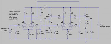
My current driver board schematic is attached.
I have used toroidal power transformers as OPT's in several experiments in the past with mixed results. Some of them just refuse to work, some work great, and most wind up somewhere in the middle. In each case the lack of primary inductance can be helped by driving the transformer with a tube circuit having the lowest possible output impedance. Best case is a big triode with very low Rp. A G1 driven pentode with some local feedback can work good too. A screen driven pentode tends to have a higher plate impedance than the same tube driven by G1, so screen drive may not be the best choice with this OPT.
Even the smallest 6BQ6GT's can easily provide the power output you are looking for. I tested a pair of 6BQ6GA's in post #654 of this thread in conventional G1 drive......about 100 watts on 500 volts. The little guys can do 70+ watts. I found the upper limit of 6BQ6GT's in screen drive several years ago.....The tube arcs over in a fatal bang at about 110 watts, but I can't find that post now.
http://www.diyaudio.com/forums/tubes-valves/133034-6l6gc-ab2-amp.html
Attachments
There is a missing term in calculating the Zaa. Zaa is a combination of reflected secondary load in parallel with the primary inductance which was not considered.
Yes.. this is exactly why i agreed that my OPT is sub-optimal. At lower frequencies, my loadline will be steeper as the primary inductance produces lower reactance. Things get better as we go up the frequency register. Hence, i also mentioned the need to couple this amp with Class D Subwoofer. Some tube-based High Pass Filter is also in the backlog. I'll focus on getting this amp to work first and perhaps try my luck later in rewinding the toroids.
I haven't reached the part where i finalize the schematic (grid-gate stopper are still missing and safety zener for the G-S of the MOSFET) and put in some feedback. I'm thinking of something along the line of Schade/Baby Huey-like, but it stretches from the input LTP to the output tube, enclosing the driver and criss-crossed as the phase is flipped by the middle driver stage. If it works, it should help reduce the effective rp of the output tube and cooperate better with the sub-optimal OPT.
I think these bias points and swings do not correspond to G2+G1 "Crazy drive"
In that case, it seems i won't be following the crazy drive scheme as it involves some additional power supply. This amp was a simplification of my previous idea that i chose to abandon earlier http://www.diyaudio.com/forums/tube...-g1-g2-driven-amp-concept-worth-pursuing.html I rekindled my interest to it since i realize i can reach PP EL34-like power with such small tube and simple power supply arrangement. I am sure someone has done something similar, George being one of them. I just haven't found any schematic yet. I haven't lurked enough inside screen driven threads.
I imagine that my Vak vs Ia characteristic curve to be close to simple G1 drive with fixed Vg2k but now it's scaled bigger as Vg2k also grows along with the increase of Vg1k. This amp won't be as linear as "crazy" drive especially somewhere in the bias region as the lines are bunched up closer (similar to remote-cutoff pentode)
The mosfets were probably Toshiba 2SK2700's which went extinct when ROHS came to be. They were my favorites at the time. I have been using On Semi NDF02N60Z's in my recent experiments, but they have been placed on the endangered species list.
Thanks a lot to Indra1 and George for the MOSFET suggestions! Now i have a list of around 10 MOSFET's which increases my chance of finding them locally. I'll be hunting in Jaya Plaza as Bandung is where i work for the time being.
Last edited:
No need to spend a new PSU just for experiment, you can still use 300V directly and use a 15-40W 220V light bulb as heat dissipator. Or use 2xNE2 and an IRF610 as ~120V regulator for the Mosfet supply. If you choose regulated supply, bias for the mosfet is only a matter of resistor divider. Similar options at higher mosfet supply voltage and current requirement to drive G2 by itself.... In that case, it seems i won't be following the crazy drive scheme as it involves some additional power supply. ...
Compared to G1 drive, of course crazy drive is more complicated, but G1 drive is not screen drive.I imagine that my Vak vs Ia characteristic curve to be close to simple G1 drive with fixed Vg2k but now it's scaled bigger as Vg2k also grows along with the increase of Vg1k. This amp won't be as linear as "crazy" drive especially somewhere in the bias region as the lines are bunched up closer (similar to remote-cutoff pentode) ...
Compared to driving G2 by itself, for 6BQ6 and most other TV sweep tubes, crazy drive gives similar output impedance, requires lower drive for both supply and swing requirements hence easier on the mosfets, presents lower risk of exceeding G2 max dissipation and has more linear response at the cost of 2 resistors and a regulator. If you want screen (G2) drive for 6BQ6, I am not aware of any better choice than Don's Crazy drive.
Understand the options a bit more, I think this time you hit on a potentially very rewarding setup. Compromising too much will easily turn it into a flop. Good luck.
may i refer you to David Berning's ....Tube amplifiers for high-end audio by The David Berning Company
Compared to G1 drive, of course crazy drive is more complicated, but G1 drive is not screen drive.
If you want screen (G2) drive for 6BQ6, I am not aware of any better choice than Don's Crazy drive.
Umm.. you are aware that i'm also driving both G2 and G1 at the same time? Wouldn't that classify as screen drive? Anyway, that will be clear in just a moment as i have simulated the input and output stage in LTSpice.
Moving on..
Step 4 - Input Stage Design
As mentioned earlier, i plan for both input and driver stage to be LTP as i need to introduce the same PS ripple on both output tube's plate to null it in the OPT. Also.. in keeping with the octal spirit, i'm faced with only two options in my tube stash: 6N9S and 6N8S. Whichever tube i chose should be able to fulfill the design constraint of getting the full output with 1Vpk or 2Vpp input. Actually, since i need to introduce feedback to the design, the open loop gain should be enough to drive the output tube with something less than 2Vpp.
Now.. choosing 6N9S will yield more gain than 6N8S.. giving more OL gain. However, 6N9S runs with less plate current, something around 1.5-2mA. So for LTP, the tail will only sink about 3-4mA. Since i'm lazy
, i prefer the simple+cheap LM317 CCS solution for the LTP but 3-4mA is not something i would have it working with. 10mA is the minimum for me. With 3-4mA i will most certainly resort to something like BJT CCS.. more component and more complexity.So.. the remaining option is 6N8S LTP.. exactly like the driver stage only we can skip the MOSFET and resistor divider part. Let's see if this option yields the gain that i need. If we look at the LTP loadline on post #9, we can see that with about 10Vpp of g1 swing, we get 150Vak swing. So that's a gain of around 15. However, unlike the driver stage, we are now driving only one grid.. This means the gain is halved to 7.5x. Actually it's not halved but rather it's split between the two triodes so the total gain is still 15x.
Anyway, 6N8S LTP has about 7.5x gain on one triode and the plate has to swing 10Vpp to ensure the driver swings the full output.. so with 6N8S LTP, 10Vpp output needs 10/7.5 = 1.33 Vpp input. This is good news as i still have some headroom left for feedback before i reach the design target of 2Vpp input.
I also added an RC filter for this input stage as it help to balance the output swing since this stage is basically a single-ended to balanced converter. This would reduce Vak (and gain) but small enough to be ignored.
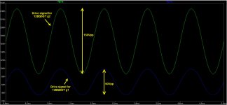
As Roxette would say, "Don't bore us, Get to the chorus!", i have attached the LTSpice simulation which shows the input+driver stage. I use IRF510 for the MOSFET as that's the model i have. The input signal is 1.2Vpp and as can be seen calculation seems to align with the simulation: i'm getting around 150Vpp swing on output to OPS G2 and 60Vpp on output to OPS G1.
10.4mA CCS current is what i get by dividing 1.25V with 120R.. a resistor in the E12 series.
Attachments
Last edited:
- Status
- This old topic is closed. If you want to reopen this topic, contact a moderator using the "Report Post" button.
- Home
- Amplifiers
- Tubes / Valves
- Screen Drive 6BQ6GT Amp - Feasibility Study