Are you going to connect the tube amp directly to a DAC, or to the Op Amp and filter, or to the filter and Op Amp that is after the DAC?
This is the first place to investigate. That is so you can know what is the output impedance of the circuit that is going to drive the tube amp. And you will also know whether your tube amp has to act as the low pass filter (when connecting directly to the DAC).
Some CD DACs have a voltage output. They need to be loaded with a medium to high impedance. But you still have to filter off the ultrasonic frequencies.
Some CD DACs have a current output. They need to drive a low Ohms resistor. They only have current compliance at very small voltage swings. That means you need gain in the tube amp.
If you load that kind of DAC with a medium to high resistance, yes, they will have more voltage output at quiet sections of the CD music, but after that they will clip at (when the CD music is medium to loud).
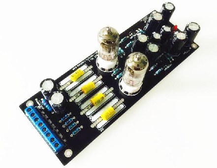
AC 12V Musical Fidelity 6j1 6AK5 tube Pre-amp Pre Amplifier
hi there,can any one help,ihave just purchased this 6j1 valve/tube pre buffer amp and the sound is terrible,at low volume the mids and highs sound just ok but the bass is muffled,can anyone help.
kind regards
Mark
hi there,can any one help,ihave just purchased this 6j1 valve/tube pre buffer amp and the sound is terrible,at low volume the mids and highs sound just ok but the bass is muffled,can anyone help.
kind regards
Mark
Ya pentode is pretty good as cathode out buffer, at least better than a triode as the gain desired can approach unity. Sonic wise some dislikes due too high 3rd or odd harmonics.
Here is a sch for cathode follower.
If you're looking for tube sound it should be harmonics rich with even and odd evenly tapered off (see TubeCad harmonic restoration articles), the distortions are purposely introduced as "overload" will create rich harmonics. I'm not sure if 6j1 fits into that, see for yourself. Maybe I'll plot other FFT designs for comparison.
Thanks for the simulation.. I tried a modified cathode follower and to my ears it sounds very clean and musical, much better than the anode version,but with unity gain..Can you kindly do a FFT analysis of this? I am new to LT spice,and i don't have tube models.
Attachments
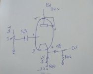
So where does the grid get its bias from?
The 1uF grid cap should be a film cap. Or, you could use an electrolytic and then you will not need a grid resistor!
You can play with a tube buffer like this until it adds just the right amount of distortion and noise to suit your own personal tastes.
The 1uF grid cap should be a film cap. Or, you could use an electrolytic and then you will not need a grid resistor!
You can play with a tube buffer like this until it adds just the right amount of distortion and noise to suit your own personal tastes.
Last edited:
No,it's not electrolytic.Both input and output capacitor are polypropylene type.
Yes.Indeed it's a learner and tweakers paradise. I noticed a small reduction in output, but the musicality is awesome... Especially shines at vocals...By the way, is it possible to skip the volume control also?
Yes.Indeed it's a learner and tweakers paradise. I noticed a small reduction in output, but the musicality is awesome... Especially shines at vocals...By the way, is it possible to skip the volume control also?
An open-grid tube will self-bias both by glass/socket-leakage and small grid currents. This has even been used commercially for special applications. Interestingly, for some range of cases, open-grid tends to bias in the higher gain zone of the tube. But I agree that here any "awesomeness" is accidental. (The most likely "awesome" case here is that the grid tends to zero-bias and clips the top of loud waves, adding "flavor".)
So where does the grid get its bias from?
The 1uF grid cap should be a film cap. Or, you could use an electrolytic and then you will not need a grid resistor!
You can play with a tube buffer like this until it adds just the right amount of distortion and noise to suit your own personal tastes.
As a newbie, please enlighten me how to play/ tweak this buffer to add distortion... Can I change the cathode resistor value / or add a resistor in series to anode and positive supply? Suggestions appreciated.
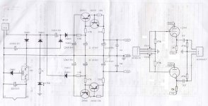
I've got two different 6J1 tube buffers off ebay that I am looking to fit inside CD players and would like to have circuit diagram. Googling seems they are based on Musical Fidelity X10-D
The first board amplifies the signal so that it distorts - the workaround is a resistor divider to reduce the input (which is what the volume control on board 2 does) but I would like to redesign it so it has unity gain.
Secondly I may want to redo for a new layout so that the circuit fits inside the CD player (currently I would have to make two holes for the valves in the top cover).
Both boards have a 3x voltage multiplies proving +/- 35 V ; I may want to put that on a separate board.
Anyway here are the two boards: (not sure if they are identical)
board 1
Hello to the OP and everyone.
Just wondering if you successfully managed to make board 1 a unity gain in the end and was it a simple job to do?
Been using one of these very similar little pre amplifiers / so called buffers and it does actually give a very nice effect in the audio chain but as you have said it does raise the gain quite considerably, to the point of distortion even depending on the material being played.
I think you are right in thinking it is pretty much a MF X10D with some variations obviously. I am quite enjoying using it though, but I would really like to get the amplification its doing down to whatever the line level is rather than it boosting the signal. I think the one Ive bought looks a neater unit than the MF as well.
These may not be everyone's cup of tea but if it makes some of us happy why not
") I do really like the effect of it even with the bog standard tubes.
I do really like the effect of it even with the bog standard tubes. Any help would be greatly appreciated.


yes, I did modify the second board, shown in original post, to be unity gain (to be precise it is slightly below 1.0 as makes no odds). The potentiometer is removed and replaced by resistors and some re-routing of components requiring the cutting of tracks.
I also added a full bridge rectifier for 12.7 V power supply (7812 with diode between pin2 and 0v) to the heaters which reduced the current draw of the circuit due to the heaters in the original being in parallel with a drop resistor. (I need to confirm this).
I also added a full bridge rectifier for 12.7 V power supply (7812 with diode between pin2 and 0v) to the heaters which reduced the current draw of the circuit due to the heaters in the original being in parallel with a drop resistor. (I need to confirm this).
yes, I did modify the second board, shown in original post, to be unity gain (to be precise it is slightly below 1.0 as makes no odds). The potentiometer is removed and replaced by resistors and some re-routing of components requiring the cutting of tracks.
I also added a full bridge rectifier for 12.7 V power supply (7812 with diode between pin2 and 0v) to the heaters which reduced the current draw of the circuit due to the heaters in the original being in parallel with a drop resistor. (I need to confirm this).
Oh wow, thanks for replying I appreciate it. Wasnt sure if I would have got a reply in this thread so I just this second put another thread up to see if anyone else could give me some ideas. Without sounding like too much of a clown as I said there I only have a basic understanding of electronics
Is it a straight forward job to do? and how could I go about it in my case. Perhaps you wouldn't mind answering in the other thread please as its a bit more specific to my unit. Was your project a success and do you still use the buffer? Your first photo of the board looked very similar to mine is that the one it worked for?
Last edited:
replied on your other thread.
I am not using the board that you have but I have a feeling I do have the circuit diagram for it.
I am still using the board in a Cyrus set up:
Dad3 -> dacmaster -> valve buffer -> cyrus pre -> smartpower x 2 ( all have psxr power supply, so that is 10 units in total)
BTW I am not a valve guru - I had the circuit diagram for the board I am using and one for a buffer (unity gain) and had a little bit of assistance/advice from somebody on a audio forum (was it here?) that allowed me to modify the circuit - the one I am using is also a pre-amplifier which has the potentiometer at the input - much like what you are asking for, but IMO is not the best solution.
I am not using the board that you have but I have a feeling I do have the circuit diagram for it.
I am still using the board in a Cyrus set up:
Dad3 -> dacmaster -> valve buffer -> cyrus pre -> smartpower x 2 ( all have psxr power supply, so that is 10 units in total
)BTW I am not a valve guru - I had the circuit diagram for the board I am using and one for a buffer (unity gain) and had a little bit of assistance/advice from somebody on a audio forum (was it here?) that allowed me to modify the circuit - the one I am using is also a pre-amplifier which has the potentiometer at the input - much like what you are asking for, but IMO is not the best solution.
- Status
- This old topic is closed. If you want to reopen this topic, contact a moderator using the "Report Post" button.
- Home
- Amplifiers
- Tubes / Valves
- 6J1 tube buffer circuit diagram