Dear all,
this is my first post here. Welcome everybody")
I recently bought a Little Bear P5-1 preamp and was not happy with it (due to several reasons like cheap components, hum, power supply operated outside its specifications etc.).
So I thought that I will build my own "Big Bear" with the tubes from the Little Bear, which are chinese 6J1 (compatible types: 5654, 6AK5, EF95).
I already build the power supply, which provides +- 32V (-> 64V) and +12V for the heaters (DC -> please no discussion about that, I want it like this).
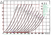
I drew a 10k load line in the "triode connected plate characteristics" in a graph of a 5654 tube (this one: http://6bm8-lab.fr/phpBB/download/file.php?id=41 which is from the Raytheon Manufacturing Company datasheet). The line goes from ~64V to ~6.4 mA.
I want the operating point to be at 1.8mA on the -1V grid line. So the cathode bias resistor should be 1V/1.8mA = 556 Ohm.
I started to play with the tubes on a breadboard building a "common cathode" circuit (the tube is connected as triode). The circuit is like this:
- 10k anode resistor connected to +32V
- 100k g1 (grid) resistor connected to -32V
- g2 connected to anode
- g3 is internally connected to cathode
- for my experiments I connected the cathode in various ways:
1. directly to -32V
2. with a 470 Ohm resistor to -32V
3. with a 1K resistor to -32V
If the cathode is directly connected to -32V then I get a anode plate voltage of ~38V and a current through the anode resistor of 2.6mA.
With a 470 Ohm resistor, I measured 0.75V across this resistor which corresponds to 1.6mA current through it.
With a 1k resistor I measured 1.1V and 1.1mA (52.9V at anode -> 0.95mA through the anode resistor).
-> So with increasing cathode resistor the voltage drop gets higher and the current lower. At 1.8mA I would have less than 0.75V and at 1V, I would have more than 0.95mA but less than 1.6mA (I guess around ~1.1mA).
First question: With the latter measurement I get approx. my -1V bias, but I was wondering why is the resistor value so far away from the theoretically calculated 556 Ohm? Further, ~1.8mA should flow through the plate, but I only calculated 0.95mA. This seems too far away from the datasheet.
BTW: I tried three different 6J1 tubes with similar results.
Second question: Should I set the bias such that a current according to the datasheet (1.8mA) is flowing to set my desired operating point or such that there is a certain voltage drop (-1V) at the cathode resistor? In any case if I cannot rely on the datasheet and the calculated resistor, then I have to use a pot and adjust it to my desired bias, right?
Third question: In the datasheet is written G2 and G3 connected to plate. How is this possible? The tube has an internal connection from G3 to the cathode. How can it be connected to plate without creating a short circuit?
Sorry for these "stupid" questions. Hope that someone can answer my questions.
Thanks!
Klaus
this is my first post here. Welcome everybody
I recently bought a Little Bear P5-1 preamp and was not happy with it (due to several reasons like cheap components, hum, power supply operated outside its specifications etc.).
So I thought that I will build my own "Big Bear" with the tubes from the Little Bear, which are chinese 6J1 (compatible types: 5654, 6AK5, EF95).
I already build the power supply, which provides +- 32V (-> 64V) and +12V for the heaters (DC -> please no discussion about that, I want it like this
).I drew a 10k load line in the "triode connected plate characteristics" in a graph of a 5654 tube (this one: http://6bm8-lab.fr/phpBB/download/file.php?id=41 which is from the Raytheon Manufacturing Company datasheet). The line goes from ~64V to ~6.4 mA.
I want the operating point to be at 1.8mA on the -1V grid line. So the cathode bias resistor should be 1V/1.8mA = 556 Ohm.
I started to play with the tubes on a breadboard building a "common cathode" circuit (the tube is connected as triode). The circuit is like this:
- 10k anode resistor connected to +32V
- 100k g1 (grid) resistor connected to -32V
- g2 connected to anode
- g3 is internally connected to cathode
- for my experiments I connected the cathode in various ways:
1. directly to -32V
2. with a 470 Ohm resistor to -32V
3. with a 1K resistor to -32V
If the cathode is directly connected to -32V then I get a anode plate voltage of ~38V and a current through the anode resistor of 2.6mA.
With a 470 Ohm resistor, I measured 0.75V across this resistor which corresponds to 1.6mA current through it.
With a 1k resistor I measured 1.1V and 1.1mA (52.9V at anode -> 0.95mA through the anode resistor).
-> So with increasing cathode resistor the voltage drop gets higher and the current lower. At 1.8mA I would have less than 0.75V and at 1V, I would have more than 0.95mA but less than 1.6mA (I guess around ~1.1mA).
First question: With the latter measurement I get approx. my -1V bias, but I was wondering why is the resistor value so far away from the theoretically calculated 556 Ohm? Further, ~1.8mA should flow through the plate, but I only calculated 0.95mA. This seems too far away from the datasheet.
BTW: I tried three different 6J1 tubes with similar results.
Second question: Should I set the bias such that a current according to the datasheet (1.8mA) is flowing to set my desired operating point or such that there is a certain voltage drop (-1V) at the cathode resistor? In any case if I cannot rely on the datasheet and the calculated resistor, then I have to use a pot and adjust it to my desired bias, right?
Third question: In the datasheet is written G2 and G3 connected to plate. How is this possible? The tube has an internal connection from G3 to the cathode. How can it be connected to plate without creating a short circuit?
Sorry for these "stupid" questions. Hope that someone can answer my questions.
Thanks!
Klaus
Last edited:
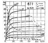
Triode connected 6j1 you got from data sheet referred to screen Vg2 @120V, so now Vg2 only 60V, hence the variations. Anyway attached is the plot for 10k loadline, Vg2 120V, it's close to your finding. I think you stick to original first since it sounds good.
Attachments
Last edited:
5654's G3 is not connected to the cathode internally. What does it have to do with 6BM8/6J1 anyway?Third question: In the datasheet is written G2 and G3 connected to plate. How is this possible?
Kinda confusing, why is there a notion of Vg2 when the pentode is triode-connected...Triode connected 6j1 you got from data sheet referred to screen Vg2 @120V...
According to this it is:5654's G3 is not connected to the cathode internally.
http://www.r-type.org/pdfs/5654.pdf
Must be typo somewhere.
I don't see any mention of Vg2 on the curves Kdre linked to??Kinda confusing, why is there a notion of Vg2 when the pentode is triode-connected...
The Raytheon datasheet referred to by the OP shows the pinouts differently.
I know... that's why I wondered why koonw brought it up.I don't see any mention of Vg2 on the curves Kdre linked to??
BTW, I was just going over the rather dated "DCdrive" design over at AX84. Do you still have the DCamp article from WW that was on your old website?
5654's G3 is not connected to the cathode internally. What does it have to do with 6BM8/6J1 anyway?
Kinda confusing, why is there a notion of Vg2 when the pentode is triode-connected...
Well the triode is not running at 60V as shown in the datasheet, Vg2 is 120V, 60V would be different data, that is what I meant. You need correct screen voltage to sim correctly, as we derived triode from pentode mode in this case I need a correct pentode plot Vg2@ 60V to derive a model first.
Attachments
Eh? That's the same datasheet I linked, isn't it? All the ones here seem to show the same pinout too.The Raytheon datasheet referred to by the OP shows the pinouts differently.
electron Tube Data sheets - 5
Probably. Send me a PM about which one it was.BTW, I was just going over the rather dated "DCdrive" design over at AX84. Do you still have the DCamp article from WW that was on your old website?
Last edited:
Check out the GE datasheet, G3 is connected to the cathode. In the end, it does not matter much since the 6J1 is not the same as the 5654, is it? Its G3 is tied to the cathode anyway.Eh? They look the same to me. All the ones here seem to show the same pinout too. Probably. Send me a PM about which one it was.
I did, please check your PM in box.
They ALL seem to show G3 connected to cathode. I guess the triode curves have a typo.Check out the GE datasheet, G3 is connected to the cathode.
I'm not familiar with it. The 'internet' seems to think they're in some way compatible.In the end, it does not matter much since the 6J1 is not the same as the 5654, is it?
Triode curves are as given on the datasheet. No need for pentode curves.You need correct screen voltage to sim correctly, as we derived triode from pentode mode in this case I need a correct pentode plot Vg2@ 60V to derive a model first.
Last edited:
Triode connected 6j1 you got from data sheet referred to screen Vg2 @120V, so now Vg2 only 60V, hence the variations. Anyway attached is the plot for 10k loadline, Vg2 120V, it's close to your finding. I think you stick to original first since it sounds good.
The datasheet that I referred in my OP post says G2 and G3 are connected to plate for the presented graph. My understanding is that therefore it cannot be @120V. Anyway I don't understand how G3 can be connected to the plate if it is internally connected to the cathode. Probably a type as others mentioned.
Did you do the simulation with LTSpice? Which model did you use? Would you like to share it with me?
Klaus
Last edited:
Yup, you are right, it's a typo, I did not squint hard enough when looking at Raytheon's pinout...They ALL seem to show G3 connected to cathode. I guess the triode curves have a typo.
5654's G3 is not connected to the cathode internally. What does it have to do with 6BM8/6J1 anyway?
As I wrote in my OP: 6J1 = 5654 = EF95 = 6AK5 (and maybe some more).
You can find many different 5654 datasheets here:
electron Tube Data sheets - 5
The ones I looked at show that G3 is internally connected to the cathode.
Best wishes
Klaus
I see... there are 6BM8 models in the Ayumi library.Well the triode is not running at 60V as shown in the datasheet, Vg2 is 120V, 60V would be different data, that is what I meant. You need correct screen voltage to sim correctly, as we derived triode from pentode mode in this case I need a correct pentode plot Vg2@ 60V to derive a model first.
Last edited:
The datasheet that I referred in my OP post says G2 and G3 are connected to plate for the presented graph. My understanding is that therefore it cannot be @120V. Anyway I don't understand how G3 can be connected to the plate if it is internally connected to the cathode.
Did you do the simulation with LTSpice? Which model did you use? Would you like to share it with me?
Klaus
No problem. The model derived directly from datasheet is per attached #2
To sim little bear I got the diagram but no values, so maybe you can label it on sch? I'll sim and see how it's using existing model (Vg2 @120V).
http://www.diyaudio.com/forums/tube...ng-inconsistencies-datasheet.html#post4603987
Well the triode is not running at 60V as shown in the datasheet, Vg2 is 120V, 60V would be different data, that is what I meant. You need correct screen voltage to sim correctly, as we derived triode from pentode mode in this case I need a correct pentode plot Vg2@ 60V to derive a model first.
Sorry for asking, but the plot shown in post #2 and this one (post #6) are different. The one in post #2 is for a triode connected 6J1 pentoded. The one in post #6 is for a pentode connected 6J1. Am I wrong with that?
My understanding is:
When connected as triode g2 is connected to the plate. Therefore, Vg2 is linked to the power supply, which is not fixed to 120V, but represented by the y-axis in the plot.
Best wishes
Klaus
Correct. I'm not sure what Koonw was talking about in post #2. Maybe he mispoke.My understanding is:
When connected as triode g2 is connected to the plate. Therefore, Vg2 is linked to the power supply, which is not fixed to 120V, but represented by the y-axis in the plot.
Originally Posted by kdre

My understanding is:
When connected as triode g2 is connected to the plate. Therefore, Vg2 is linked to the power supply, which is not fixed to 120V, but represented by the y-axis in the plot.
Correct. I'm not sure what Koonw was talking about in post #2. Maybe he mispoke.
Well it's the way triode model is derived. It is possible for more than one triode model to be generated depending on the operating points. So you were given a triode connected pentode do you know what model you have being given? Is it actual test gear plot or derived from Pentode model (without test gear)? Say if derived from Pentode there must a specific Vg2, different Vg2 generate different triode model (correct me if I am wrong). As far I know to sim correctly especially with Pentode model, one must use a model based on very close Vg2 actually used.
Since the modelling is not unique therefore it's possible for different triode connected pentode model hence the variation. This is what I suspected for variation, maybe I am wrong. If you're not simulating it does not matter really.
Correct. I'm not sure what Koonw was talking about in post #2. Maybe he mispoke.
But his main argument to answer my questions was that I have 60V instead of 120V which is why I measure cathod voltages/currents that are far away from what the datasheet says.
So, if his main argument is not valid, then my questions from the OP are still unanswered
Should not my measurements be much closer to the datasheet? (Measurement: Rc: 1k, Uc:1.1V, Ic:0.95mA;
Datasheet: Rc 556Ohm, Uc: 1V, Ic: 1.8mA;
Ra: 10k)
Klaus
Yes and no. The datasheet curves tend to be less reliable at low voltages where the tubes were seldom used. When I draw the same load line I see the -1V intersection as being closer to 2mA, meaning a 500R cathode resistor. Nevertheless, your measrements do look a bit further off than I would expect. Are you sure you have a 10k anode resistor and not something larger? It's also possible that your valve samples are rather old and worn out!Should not my measurements be much closer to the datasheet? (Measurement: Rc: 1k, Uc:1.1V, Ic:0.95mA;
Datasheet: Rc 556Ohm, Uc: 1V, Ic: 1.8mA;
Ra: 10k)
- Status
- This old topic is closed. If you want to reopen this topic, contact a moderator using the "Report Post" button.
- Home
- Amplifiers
- Tubes / Valves
- 6J1 biasing inconsistencies with datasheet