What you see inside the "guts" are terminal strips, turret boards, and tag strips. Talk to Jim McShane, as he's a go to guy for tubes and many of the parts that support them. 
The Cardas jacks and posts are good, but, from my perspective, too costly. A really good twin binding post for relatively little money is the Superior Electric brand from Allied Electronics. The late Bob Crump preferred those posts to the "fancy/shmancy" stuff.
If you can kill the ceramic socket order, do so! Ceramic conducts vibration and PTFE (teflon) creeps. Well made mica loaded phenolic, like Belton, is what I favor and it costs less too.")
If you want to use fancy power cords and IEC power connectors, be my guest. I despise them, as they are just another mechanical connection that can cause trouble. I like "captive" power cords, with appropriate strain relief. We are going to put ferrite beads on the primary wires of the AnTek power trafos. Those inexpensive beads (IMO) are every bit as good as an expensive power cord in suppressing EMI/RFI.
In case you haven't noticed, I'm a cheapskate. I look for very good performance at relatively modest expense. I'm more than willing to spend, but I demand my money's worth.
The Cardas jacks and posts are good, but, from my perspective, too costly. A really good twin binding post for relatively little money is the Superior Electric brand from Allied Electronics. The late Bob Crump preferred those posts to the "fancy/shmancy" stuff.
If you can kill the ceramic socket order, do so! Ceramic conducts vibration and PTFE (teflon) creeps. Well made mica loaded phenolic, like Belton, is what I favor and it costs less too.
If you want to use fancy power cords and IEC power connectors, be my guest. I despise them, as they are just another mechanical connection that can cause trouble. I like "captive" power cords, with appropriate strain relief. We are going to put ferrite beads on the primary wires of the AnTek power trafos. Those inexpensive beads (IMO) are every bit as good as an expensive power cord in suppressing EMI/RFI.
In case you haven't noticed, I'm a cheapskate. I look for very good performance at relatively modest expense. I'm more than willing to spend, but I demand my money's worth.
Eli,
Carefully peeping in so as not to disturb - but where did you upload the 6922 cascode? Cannot find it in this thread; elsewhere or must I go wash my eyes out?
Thanks!
"Once more, into the breech!"
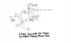
An added refinement, for better parasitic oscillation suppression, is to cement a tiny ferrite bead to the socket surrounding the "upper" triode's grid lug. The bead should not make contact with any socket lug.
The "upper" triode's grid in a cascode is supposed to be at AC ground. Therefore, I eschew a resistive stopper.
Attachments
ok yes go for 6922 because i have some 7503 the highest end of these tubes.
power 3 cables are just used for years on other stuff i have sold.
see the 2 p101 sitting here now are fantastic neutral but look lifeless. just 2 aluminum blocks .
picture 2 tube mono blocks that are going to be show stopper's.
they will command so much attention and will be visualy stunning, everything must be up to par as well . i have used the cardas binding posts for years and love them
you had mentioned the maida board, i goggled that and found a blank board on a site pete millet. not sure if it is the right one because he says good for pre amps but not needed in power amps.
http://www.pmillett.com/images/shvreg_pcb_big.jpg
Last edited:
you had mentioned the maida board, i goggled that and found a blank board on a site pete millet. not sure if it is the right one because he says good for pre amps but not needed in power amps.
Wade your way through this thread.
The screen grid current in power O/P tubes is small in comparison to the plate current. Rigidly fixing g2 B+ potential in full pentode mode "finals" contributes substantially to open loop linearity. The more linear the circuit is, from the outset, the better the performance of the NFB loop. Smaller error correction signals are what the whole thing is about. In particular, regulated g2 B+ reduces the amount of highly irritating IMD generated.
ok yes go for 6922 because i have some 7503 the highest end of these tubes.
I can find no reference for 7503.
Perhaps you mean 7308/E188CC.Using the cascode presents another regulation challenge. Fortunately, a little TO92 case LR8 3 terminal regulator in each monoblock disposes of the issue. Power supply rejection ratio (PSRR) is abysmally poor in cascodes. Therefore, cascode B+ must be regulated.
I think you mean 7308 and not 7503?
ok yes go for 6922 because i have some 7503 the highest end of these tubes.
power 3 cables are just used for years on other stuff i have sold.
see the 2 p101 sitting here now are fantastic neutral but look lifeless. just 2 aluminum blocks .
picture 2 tube mono blocks that are going to be show stopper's.
they will command so much attention and will be visualy stunning, everything must be up to par as well . i have used the cardas binding posts for years and love them
you had mentioned the maida board, i goggled that and found a blank board on a site pete millet. not sure if it is the right one because he says good for pre amps but not needed in power amps.
http://www.pmillett.com/images/shvreg_pcb_big.jpg
"Once more, into the breech!"
An added refinement, for better parasitic oscillation suppression, is to cement a tiny ferrite bead to the socket surrounding the "upper" triode's grid lug. The bead should not make contact with any socket lug.
The "upper" triode's grid in a cascode is supposed to be at AC ground. Therefore, I eschew a resistive stopper.
They used to implement ferrite beads into ham radio transmitters and receivers to suppress parasitics and you can pick those up for pennies and it makes a worthwhile sonic improvement especially in higher gain stages.
I'm going to do this on the Mac Mc240 I am rebuilding.
I can find no reference for 7503.
Using the cascode presents another regulation challenge. Fortunately, a little TO92 case LR8 3 terminal regulator in each monoblock disposes of the issue. Power supply rejection ratio (PSRR) is abysmally poor in cascodes. Therefore, cascode B+ must be regulated.
sorry guys late night typo
yes 7308 amperex 1960 nos tubes
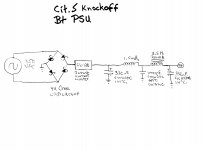
The capacitor after the CL-130 might be a bit large for it. The data sheet recommends 145uF max when the supply is 240 vac. Maybe the CL-180 would be better. C max = 400uF at 240vac.
http://www.farnell.com/datasheets/85914.pdf
On the other hand, it might be fine. I don't have direct experience with these devices.
Also, the middle capacitor looks a bit too small to really be useful. I'm not sure what your intention is with this value.
http://www.farnell.com/datasheets/85914.pdf
On the other hand, it might be fine. I don't have direct experience with these devices.
Also, the middle capacitor looks a bit too small to really be useful. I'm not sure what your intention is with this value.
The capacitor after the CL-130 might be a bit large for it. The data sheet recommends 145uF max when the supply is 240 vac. Maybe the CL-180 would be better. C max = 400uF at 240vac.
http://www.farnell.com/datasheets/85914.pdf
On the other hand, it might be fine. I don't have direct experience with these devices.
Also, the middle capacitor looks a bit too small to really be useful. I'm not sure what your intention is with this value.
You have to look at the max. current allowed through NTC thermistors, in this situation. It's highly likely, in this case, for the device to run relatively cool and continue to introduce some resistance, in the "steady state". While the B+ rise delay introduced by the thermistor is small, it's enough to allow a SS rectified bias (C-) supply to turn on, fully.
The 1.5 mH. RFC and the 1000 pF. cap. comprise a "hash" filter. The "hash" filter suppresses HF noise riding on the B+ rail, regardless of said noise's origin. Such HF noise could sneak into the reservoir cap., via the main filter choke's winding capacitance. A more "black" background is the result of installing a "hash" filter.
BTW, large valued cap. I/P filters are inherent "hash" generators. Look at the ripple current waveform and apply Fourier's Theorem.
@Eli, you posted a "new" scheme to my eyes, will try it in my next build.....in my case, will usually start with smaller cap as first cap and then make the last cap the biggest...
Don't use a large valued cap. at the I/P of a CLC filter, when the power trafo is not "hefty". Trying to pull more than 50% of the rectifier winding's rated RMS current is asking for big trouble. The bigger that 1st cap. gets, the worse I2R heating in the rectifier winding becomes. Also, the bigger that 1st cap. gets, employing a "hash" filter becomes ever more important.
^ sure thing, i use voltage doublers and bigger than normal power traffos, with low dc resistance secondaries.... have a hundred or so MUR860's that i use in my builds...https://www.fairchildsemi.com/datasheets/RU/RURP860.pdf
Eli,
It might be here but I have not found it.
Where in this circuit (Cit 5) does the I/P roll off occur
at under 30Hz?
Cheers,
Sync
It might be here but I have not found it.
Where in this circuit (Cit 5) does the I/P roll off occur
at under 30Hz?
Cheers,
Sync
GKF,
Frankly, I don't think you will be happy with the no better than marginal MK3.
Most, if not all, of us here face budget realities. Quite nice results can be obtained from Mullard style circuitry and decent, if unspectacular, O/P "iron". IMO, the best "vintage" implementation of Mullard style is the H/K Cit. 5 (schematic uploaded). The Cit. 5 does use high gm small signal types.You could "copy" the Cit. 5 around Hammond 1650P O/P transformers. Roll the deep bass off just below 30 Hz. at the circuitry's I/P, to protect against core saturation. Please keep in mind that the lowest note a "standard" double bass plays is 41 Hz.
The 12BY7 the Cit. 5 employs as its voltage amplifier is out of production and, IMO, the available stock should be reserved for amps already in existence. That fact set is really a non-issue as I've uploaded a 6922 cascode voltage amplifier schematic that's specifically intended to dispose of the matter.
We are looking for the 30Hz cut off? or
we could look at it like a hi-pass at 30 Hz.
If I recall the math should look something like this:
Fc=1/2PiRC, 270 Ohm resistor, 100uF (2 x 200uf in series)
fc= 1/ 6.28*270x.000,100
fc=1/1,695.6*.000,100
fc=1/.16956
fc=5.9Hz
So we just high pass at 5.9 Hz?
Or roughly 10 times less than the power frequency of 60Hz.
PSUD2 does a marvelous job with the math. It's a free download and it's fun to tinker with. A large capacitor coming out of the bridge isn't necessarily a bad thing if the DC resistance of the transformer secondary is enough to limit the turn-on surge current through the diodes to their design value.
- Status
- This old topic is closed. If you want to reopen this topic, contact a moderator using the "Report Post" button.
- Home
- Amplifiers
- Tubes / Valves
- design advise