Yes well, if your using the best available ferrite for that frequency for core loss, then I guess the core shape is the next variable that may provide more effective area for the same external volume. It's not as if you need a core shape that allows a former with 6 pins on each side! But you probably can't get 3C98 in something like a simple P core.
What was your estimated core loss for the PQ core size you have? I recall often ending up with a coil that could swim inside the core, just keep core loss reasonable.
Just checking - Rac ~3 x Rdc for 0.23mm wire at 90kHz. That indicates you may be down half a watt.
Would foil be easier to work with if you had it?
Very high Q inductors are hard to make. Even a low loss ferrite core will have a significant contribution, but Litz wire is a requirement, especially on the lowest layers (proximity effect) and near the gap (eddy currents).
Foil doesn't help much because current is confined to the edges, for the most part. Skin effect works in 2D just as in 3D.
There's a company that claims to make a sheet-like product that's somehow woven to fix this (effectively, Litz made of strip, or simply woven into a wide web), though that would be overkill for this.
This is basically the sole reason such converters don't see use -- their operation may be simple, but the control is kind of tricky (because of the high Q) and the inductor and capacitors are much larger, and much more expensive, than a conventional transformer based design.
Tim
About 0.9W.What was your estimated core loss for the PQ core size you have?
All the online calculators and nomograms seem to agree: for 0.23mm/90kHz, the difference between Rdc and Rac is negligible.Just checking - Rac ~3 x Rdc for 0.23mm wire at 90kHz. That indicates you may be down half a watt.
Of course, this is not an isolated wire, and there are also crowding/proximity effects, but they are of the same order as the "simple" skin effect, ie more or less negligible here
No, I have foil available, but it would make the eddy currents ten times worse in the vicinity of the gaps, and that's already the dominant loss mechanism (in my final RM6 version anyway)Would foil be easier to work with if you had it?
True, but with modern materials, you can achieve small miracles: the tiny RM6 core handles an apparent power of 215W without trouble, and the tuning capacitors aren't huge either despite being of an oldish technology (the bulk of the capacitors are the filtering ones).Very high Q inductors are hard to make. Even a low loss ferrite core will have a significant contribution, but Litz wire is a requirement, especially on the lowest layers (proximity effect) and near the gap (eddy currents).
.../....
This is basically the sole reason such converters don't see use -- their operation may be simple, but the control is kind of tricky (because of the high Q) and the inductor and capacitors are much larger, and much more expensive, than a conventional transformer based design.
A modern PP one would be much more compact.
Another thing to consider is that a 300Vpp sinewave is much more benign than 300V/100ns edges.
Of course, it would be silly to use that kind of scheme for hundreds of watts, but for a few watts, it is perfectly practicable
Attachments

Arrgh, I had typed in 2.3mm, not 0.23mm - sorry.
Would you be better off to go to an RM8 or larger? The mT level would be lower, and you may be able to position the coil away from the air-gap (if you were able to get the centre leg suitably ground so that the outer sections had no gaps).
Would you be better off to go to an RM8 or larger? The mT level would be lower, and you may be able to position the coil away from the air-gap (if you were able to get the centre leg suitably ground so that the outer sections had no gaps).
Yes, it is one of the options I already tested:Would you be better off to go to an RM8 or larger? The mT level would be lower, and you may be able to position the coil away from the air-gap (if you were able to get the centre leg suitably ground so that the outer sections had no gaps).
It did work, and very comfortably but it was too large and it would have had to stay off-board.Next attempt was based on a RM8, N67 core, also with a good number of turns. This one worked quite satisfactorily, exceeding the expectations, the only problem was the bulk: it couldn't physically replace the previous ones.
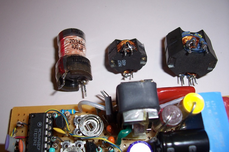
In the mean time, I also tested the RM6/N49 core with real litz wire.
Unfortunately, the one I have is thicker, and I only managed 23 turns.
This resulted in a peak induction of 340mT, which is uncomfortably high, yet it was still the best-performer, capable of reaching 315V on its nominal load without excessive heating of the copper or the iron.
Clearly the way to follow: appropriate litz wire + good ferrite like N49.
Combined with the alternate MOSFet power stage, it could easily exceed 10W output with a reasonable efficiency.
That said, for more modest power levels like 2 or 3W, there is no need to go to such lengths: the standard drum choke I showed would already be vast overkill
All the online calculators and nomograms seem to agree: for 0.23mm/90kHz, the difference between Rdc and Rac is negligible.
Of course, this is not an isolated wire, and there are also crowding/proximity effects, but they are of the same order as the "simple" skin effect, ie more or less negligible here
Nooo!
 Proximity effect is considerably stronger than skin effect, to the tune of an order of magnitude!
What matters is how many amp-turns there are above a given wire/layer. In an inductor, the first layer sees all the amp-turns of the layers above it, so it's a worst case condition.
In a transformer, you have some freedom to control this, by interleaving the windings: if every primary and secondary layer is interleaved alternately, the amp-turns cancel out after each layer pair, and you can get quite good efficiency without too much worry over wire size (such a windup is more labor-intensive, though, and may have too much capacitance / too low an impedance for an application).
If you've never obtained a NEWT catalog, I do recommend it, even if you don't intend on purchasing industrial quantities of wire.
NEWT, what the heck? Sounds like a Harry Potter acronym... nope: Custom Wire and Cable Manufacturer | Custom Cables | Litz Wire |Specialty Wire and Cable | New England Wire
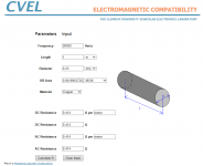
Specifically, this info is relevant:
http://www.newenglandwire.com/~/media/Files/Litz_Theory.ashx?la=en
Current crowding affects strands within a Litz cable, just as well as layers in a transformer (and the effect is compounded for multilayer inductors wound with it!).
Notice that the "single strand Rac/Rdc" is very, very, very nearly 1.0 in all the cases. It gets exponentially worse when strands are packed together (whether in a cable or a winding), which is why so many strands, of such fine wire, are desirable for these applications.
To be fair, I suppose NEWT has some vested interest in selling finer constructions, but they're also pulling that reference from Terman, so I don't see any reason to doubt it.
True, but with modern materials, you can achieve small miracles: the tiny RM6 core handles an apparent power of 215W without trouble, and the tuning capacitors aren't huge either despite being of an oldish technology (the bulk of the capacitors are the filtering ones).
A modern PP one would be much more compact.
Another thing to consider is that a 300Vpp sinewave is much more benign than 300V/100ns edges.
True, but that's only relevant at the output side; and you still have some reverse recovery noise from the diodes there. And the input side is extremely noisy because it's handling a full square wave.
That said, I'd rather have it this way, than the other way around (HV square wave, say from a 300-->12V buck converter), because high voltage switching tends to be much harder to deal with than low voltage switching!
Tim
I recall that some core types had a noticeably wider winding width for the same effective core area, and hence the number of layers could be minimised. Anyone know how RM compares for that, or if there are significantly better types
Elvee, were you able to determine what litz format gave a proximity Rac minimum for 5 layers?
Elvee, were you able to determine what litz format gave a proximity Rac minimum for 5 layers?
There are very elongated form factors, typically in EI or EE shape, intended for flyback converters (but the problematic is partly identical here, at least for the Rac part). RM, potcores, X cores, etc tend to have a more or less square winding window because it is a good trade off between copper and iron parameters.I recall that some core types had a noticeably wider winding width for the same effective core area, and hence the number of layers could be minimised.
Anyone know how RM compares for that, or if there are significantly better types
I tend to shun extreme shapes, because they depart from the ideal canonical shape (minimizing the materials quantities and field heterogeneity), ie a ring of conductive turns enclosed in a doughnut of magnetic material, or the exact opposite, more or less a toroidal inductor.
Problem with these ideal shapes: they need to include a gap. Metal powder cores would be ideal in this respect, because the gap is distributed but unfortunately for extreme boost ratios like here, the grain fineness is to coarse and the conductivity too high, leading to high losses (the same applies to extreme flyback ratios).
These "abnormal shapes" might be worth considering here
The best theoretical format would always have the target of filling the whole window area with copper, provided of course any arbitrarily fine individual strand gauge is allowed, which is not the case in practice.Elvee, were you able to determine what litz format gave a proximity Rac minimum for 5 layers?
Here, since the frequency is only moderately high, it is probable that filling the window with 35t of the best litz wire would be optimal (but I wouldn't swear on it), but at some higher frequency this wouldn't be true anymore.
I started to have that proximity issue in the early 80's with class E inductor at 2MHz, but at that time I was pretty much stuck with P cores due to lack of choice. The unitrode design seminar books were a very accessible form of design info on smps and proximity from the late 80's.
There is a design plot showing Rac versus number of layers resulting from proximity effect - the curves identify a slightly varying minima as the number of layers increases - it was that set of curves that I thought would be able to identify a target for litz configuration.
Gapping the centre core leg only is obviously the better path to take, but gap related loss may mean sacrificing a little winding window in order to pad the inner turns layer away from the gap.
I was just looking back to see when the Unitrode seminars started to focus on proximity practicalities - interestingly Dixon was intimating that litz wasn't the way to go. I recall that it was better to go multifilar - even though the number of layers increased, total Rac went down.
https://www.ti.com/seclit/ml/slup205/slup205.pdf
https://www.ti.com/seclit/ml/slup205/slup205.pdf
Yes, that sounds logical: if you make a total mess of a multifilar "scramble" winding, every filament will occupy randomly every possible position in the window.
I see two issues with such an approach: the filling factor will be impacted, and at some random places, the voltage between two conductors will be very high.
Not a problem for low-voltage applications, but at 200~300V, the fragile isolation of 0.02mm wires will certainly flash here and there
I see two issues with such an approach: the filling factor will be impacted, and at some random places, the voltage between two conductors will be very high.
Not a problem for low-voltage applications, but at 200~300V, the fragile isolation of 0.02mm wires will certainly flash here and there
I think the idea is to use flat single-layer multifilar. I recall that 2-4 filar wasn't toooo onerous to wind on a former, with a single layer of 3M 1350 tape of the right width to keep each layer in place. Going to an EFD type core with relatively wide winding width then became the target.
- Status
- This old topic is closed. If you want to reopen this topic, contact a moderator using the "Report Post" button.
- Home
- Amplifiers
- Power Supplies
- A small resonant HV converter: Q-Conv