Hi All,
Ok so this is my first post here so Hi. Picked up an Audioromy m828a FU29 tube amp from ebay - came quick, seems pretty well made.
I wanted to get the Bias and Balance right before I started using it extensively, so went about looking at it's guts. It seems the one I have differs from the schematics I have seen and the photos of the PCB apart from one person on this forum about a year ago who had gone about a similar question.
It does seem that the information been put out by some of the sellers of this amp is not compatible with what is actually in the unit. I wasted a lot of time stupidly trying to bias via the cathode, as there seemed to be a 0.4ohm resistor there (evidently not really). I could not get a real mv reading across to determine adjustment to get to 50ma total on the combined cathode.
So the 829b tube has a single common cathode and two anodes, essentially two tubes in one. It looks like the more recent versions of this Audioromy amp have no resistors for the cathode to determine the current here, but instead uses 1ohm resistors on the anodes for each half of the tube?
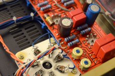
The attached image of the PCB area for one tube (from the other thread but is same as mine) shows the anode resistors and the white wires heading off to the top of the tubes.
The other attachment shows the instructions that have been sent around from the various sellers about how to bias the unit.
I suppose my post is here to highlight this disparity to anyone else who may have been confused about this and also to ask, can I adjust the bias and balance correctly via the supposed 1ohm anode resistors???
If it were a case of a simple in at cathode, out at anode analogy, I see how it wouldn't make any difference where the mv reading is taken? However what with the screen, grid in between the two, absorbing some of the juice, this reading might not be correct?
When talking about tube ratings, is the 50ma applicable to this tube in terms of cathode current or is it a more general cathode / anode current, making the location where this reading is taken irrelevant?
I am new to tubes since about a few weeks ago, so have a hell of a lot to learn and will refresh my basic electronics knowledge in the process.
Appreciate any help on this as I am going to attempt to bias / balance these tubes tonight and do it properly (ideally a self balancing circuit would be my solution?)
Cheers,
Rich.
Ok so this is my first post here so Hi. Picked up an Audioromy m828a FU29 tube amp from ebay - came quick, seems pretty well made.
I wanted to get the Bias and Balance right before I started using it extensively, so went about looking at it's guts. It seems the one I have differs from the schematics I have seen and the photos of the PCB apart from one person on this forum about a year ago who had gone about a similar question.
It does seem that the information been put out by some of the sellers of this amp is not compatible with what is actually in the unit. I wasted a lot of time stupidly trying to bias via the cathode, as there seemed to be a 0.4ohm resistor there (evidently not really). I could not get a real mv reading across to determine adjustment to get to 50ma total on the combined cathode.
So the 829b tube has a single common cathode and two anodes, essentially two tubes in one. It looks like the more recent versions of this Audioromy amp have no resistors for the cathode to determine the current here, but instead uses 1ohm resistors on the anodes for each half of the tube?
The attached image of the PCB area for one tube (from the other thread but is same as mine) shows the anode resistors and the white wires heading off to the top of the tubes.
The other attachment shows the instructions that have been sent around from the various sellers about how to bias the unit.
I suppose my post is here to highlight this disparity to anyone else who may have been confused about this and also to ask, can I adjust the bias and balance correctly via the supposed 1ohm anode resistors???
If it were a case of a simple in at cathode, out at anode analogy, I see how it wouldn't make any difference where the mv reading is taken? However what with the screen, grid in between the two, absorbing some of the juice, this reading might not be correct?
When talking about tube ratings, is the 50ma applicable to this tube in terms of cathode current or is it a more general cathode / anode current, making the location where this reading is taken irrelevant?
I am new to tubes since about a few weeks ago, so have a hell of a lot to learn and will refresh my basic electronics knowledge in the process.
Appreciate any help on this as I am going to attempt to bias / balance these tubes tonight and do it properly (ideally a self balancing circuit would be my solution?)
Cheers,
Rich.
Attachments
These amplifiers depend on who built them as far as components in use are concerned. Pinch of salt is a good saying.
I set these up by inserting a 1R 2W resistor in series with the anodes. Using properly insulated test leads and two DVM's, set the voltage drop across each resistor to 25mV. There is some confusion as to which pre-set is which, this will become apparent very quickly whilst setting the valves up. BEWARE there is DANGEROUS voltage on the anodes!
The 1R can stay for future use as they do not affect the sound.
Hi
Fathers day here in Australia and i managed to get a whole morning to myself in the shed! I took the backplate of my Audioromy and had some fun with the soldering iron.
I replaced the 4 blocking caps (big red rectangular ones in the pic) with something much more exotic (german, look like cotton reels)
I soldered in 1.1 ohm resistors form the cathode pin4 to ground
I then set about Biasing - the voltage drop acrid the cathodes was easy to set (outside pot in the picture above) and i set it to 55mV which equates to 50 mA to the cathode.
Then i put the DVMs across the two anodes (test points 2b+ and 2b- in picture above) and tried to adjust the inside pot to get a reading close to zero - this was impossible. The readings fluctuated between say -200mv and plus 200m - with peaks of say 1v either side. I adjusted so the fluctuations were the same magnitude either side of the sign.
My Questions to JonSnell and others..
1) Is this normal..? the bias text suggest that you should adjust to as close to zero as possible..
1b) doh - just realised - should i have been on AC voltage settings?!!
2) If i put a 1.1ohm anode resistors in series with the anode leads to measure voltage across - will this affect the operation of the amp.
3) Do i attach the anodes after their attachment to the resistor..?
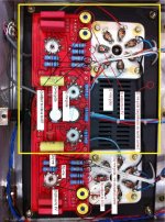
4) i have the red circuit board - is this an early model then? I have seen some with green boards and fewer components
Amp sounds good - some hum but that disappears if you crank it up..
5) If i wanted to get rid of the hum - where do i start to look?
cheers
Fathers day here in Australia and i managed to get a whole morning to myself in the shed! I took the backplate of my Audioromy and had some fun with the soldering iron.
I replaced the 4 blocking caps (big red rectangular ones in the pic) with something much more exotic (german, look like cotton reels)
I soldered in 1.1 ohm resistors form the cathode pin4 to ground
I then set about Biasing - the voltage drop acrid the cathodes was easy to set (outside pot in the picture above) and i set it to 55mV which equates to 50 mA to the cathode.
Then i put the DVMs across the two anodes (test points 2b+ and 2b- in picture above) and tried to adjust the inside pot to get a reading close to zero - this was impossible. The readings fluctuated between say -200mv and plus 200m - with peaks of say 1v either side. I adjusted so the fluctuations were the same magnitude either side of the sign.
My Questions to JonSnell and others..
1) Is this normal..? the bias text suggest that you should adjust to as close to zero as possible..
1b) doh - just realised - should i have been on AC voltage settings?!!
2) If i put a 1.1ohm anode resistors in series with the anode leads to measure voltage across - will this affect the operation of the amp.
3) Do i attach the anodes after their attachment to the resistor..?
4) i have the red circuit board - is this an early model then? I have seen some with green boards and fewer components
Amp sounds good - some hum but that disappears if you crank it up..
5) If i wanted to get rid of the hum - where do i start to look?
cheers
I find it more accurate to place a 1R resistor of say 2W in size in series with each anode and the transformer for balancing the valve. BE EXTREMELY CAREFUL NOT TO ELECTROCUTE YOURSELF as DC volts won't let you let go and will fry you!
If the valve is unbalanced say 20mA on one side and 28mA on the other half, this will induce hum at twice mains frequency as the power supply uses a full wave bridge. In some models, a half wave bridge was employed and there was no hum issues.
Using the test point 2b+ and 2b- assumes the output transformer is symmetrically wound and some again are not and give a different DC resistance from side to centre.
There will be low frequency ramping due to the design of the coupling and power supply limitations so a motor-boating effect is to be expected, on some models.
Set the balance as best you can then reset the bias and then the balance until you are happy and the hum has gone. If it won't set then try another valve.
The bias voltage must vary with any changes in mains input fluctuations or you will get problems with over heating or under running.
Hope that helps.
Not the best design in the world!
Thanks Jon. So to be clear, the 2w 1 ohm resistor can be soldered from where the anode leads leave the red PCB (near TP2a/2b) in series with the anode wire - so 4 lots of resistors. I am looking for 25 mv on my DVM which equals 25mA on each Anode (assuming 1ohm resistor) correct?
I hear you on the high DC voltages - i connect to the TPs with crocodile clips when the unit is off and i also wear thick rubber gloves when it is on.
One other question i have for you - Pin 4 / cathode looked like it went to ground in the photo of the circuit (you can see a small wire from Pin 4 to the PCB) - i removed that wire and wired the cathodes straight to the ground (the earth pin on the power lead) via a 1.1 ohm 2W resistor to allow me to measure voltage and hence current across that resistor - is that design ok? It all works.
I have a new set of (NOS) russian GU29 valves - when i tried them they glowed blue/white with fluorescence - didn't seem normal so i unplugged them straight away - i will take a picture for you!
I am sure they need biasing etc so i will try that with the NOS russian valves - or are they duff?. At least i have eliminated the cherry plating i was getting on the RCA valves it came with.
Also what you said about the mains input fluctuations makes sense - i am sure the consistency of our mains voltage in Adelaide is lousy - we have a lot of solar and wind generation (50% by 2018 they reckon) - but i do see lights dim frequently in the house when loads get turned on... maybe some sort of mains conditioner is needed..
Thanks for your help. I will try an order some spare parts from you next time i am home in Bristol.
Digging up this old thread as I have some info that relates to this amp. Just got one on my bench for repair- blows fuses on power up.
What rating is the input fuse? This one had 2A. Inrush current was massive, yet all power supply components test fine and unit plays stable for hours after brought up slowly on a Variac & pulls just over 1A when operating. Then I noticed the first filter cap in the CRC filter plate supply was 270 µF! Way, way too much. Replaced it with a 50 µF, inrush greatly reduced. Added a thermistor (CL 80) to knock down the 10+ percent dc voltages I’m measuring. Heaters are presently 13.2 VAC and B+ is 455 VDC with 120VAC in. Filter caps only rated at 450- yikes!
Also note- the AC switch was wired on the neutral side. Switched neutral (AKA earth, return or ground) wires are a hazard, so I rewired it, putting the switch after the fuse on the hot side.
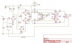
There seems to be some variations in the schematic. To set bias and balance, I just measure Vdrop across the resistors in series with each plate lead. Mine came with 1.0 Ω sense R's so super easy, target for 25mA. I’m considering inserting a 1 ohm 1/2W in series with the cathodes as a fuse resistor for safety.
Some very good info on this amp with the correct schematic-
Analog Sauce: The Audioromy M828-A – Engineering Radio
What rating is the input fuse? This one had 2A. Inrush current was massive, yet all power supply components test fine and unit plays stable for hours after brought up slowly on a Variac & pulls just over 1A when operating. Then I noticed the first filter cap in the CRC filter plate supply was 270 µF! Way, way too much. Replaced it with a 50 µF, inrush greatly reduced. Added a thermistor (CL 80) to knock down the 10+ percent dc voltages I’m measuring. Heaters are presently 13.2 VAC and B+ is 455 VDC with 120VAC in. Filter caps only rated at 450- yikes!
Also note- the AC switch was wired on the neutral side. Switched neutral (AKA earth, return or ground) wires are a hazard, so I rewired it, putting the switch after the fuse on the hot side.
There seems to be some variations in the schematic. To set bias and balance, I just measure Vdrop across the resistors in series with each plate lead. Mine came with 1.0 Ω sense R's so super easy, target for 25mA. I’m considering inserting a 1 ohm 1/2W in series with the cathodes as a fuse resistor for safety.
Some very good info on this amp with the correct schematic-
Analog Sauce: The Audioromy M828-A – Engineering Radio
Attachments
i have repaired this amp years ago...
the G2 supply must be well decoupled and never to exceed 200 volts dc....a mosfet power source follower will do very well...
on hindsight, i would install a 5894 tube in place of the 829b, this tube has a single filament and cathode structure so that tube balance is superior to any 829b..
these amps sound very good..
- Status
- This old topic is closed. If you want to reopen this topic, contact a moderator using the "Report Post" button.
- Home
- Amplifiers
- Tubes / Valves
- Audioromy M828A/829B FU29 Bias/Balance Help