Thanks for that,
I also collected an X100-C service manual, but too big for forum attach.
I'll figure how to break it up later...
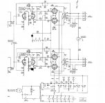
My chassis is X100-3, circuit somewhere between x100-3 and x101.
No single document I have matches it exactly...
If you substitute an EL84 without 7189's "IC" connection to that
otherwise irrelevant/unused pin, You may have to bridge that
on the socket yourself. My JJ EL84's had it, so I didn't have to.
On mine, Fisher definitely made connections to the pin in question.
Schematics and service manuals don't always show this stuff.
I also collected an X100-C service manual, but too big for forum attach.
I'll figure how to break it up later...
My chassis is X100-3, circuit somewhere between x100-3 and x101.
No single document I have matches it exactly...
If you substitute an EL84 without 7189's "IC" connection to that
otherwise irrelevant/unused pin, You may have to bridge that
on the socket yourself. My JJ EL84's had it, so I didn't have to.
On mine, Fisher definitely made connections to the pin in question.
Schematics and service manuals don't always show this stuff.
Attachments
Last edited:
My 7189 substitutes are JJ EL84. I recall ordering
a quartet from Parts Express. Rated higher than
the usual EL84 plate voltage, at least equivalent
to "EL84M". They did not disappoint.
The JJs do okay, but the Sovtek EL84M is probably a better choice. It's the current production version of the well regarded 6P14P-EV tube that was available for a while, and has no problem with the higher dissipation a 7189 is often required to take. Higher voltage - of and by itself - is not an issue, it's the current and the dissipation wattage that is the tube killer.
Also, Eli's suggestion regarding the output tube bias/tube heater setup in the amp is a good one. Yes, the stock setup works, but not as well as a regulated supply for the heaters and a proper cathode bias setup for the power tubes.
There are a number of improvements you can do to that unit that won't break the bank and can improve performance and reliability significantly. However they do require a reasonably skilled tech or DIYer to perform. Also remember - that unit is 50-ish years old. It is going to need some TLC, and all new caps is a good start.
Send EL84M (dead OK) for XRay comparison against original 7189 and JJ EL84 (I have these two) and we can debate. I also have 16P- something, I'll have a looksee tonite.
Most of my stash already illuminated here:
http://www.diyaudio.com/forums/tubes-valves/130597-grid-screen-alignment-x-rays.html
Most of my stash already illuminated here:
http://www.diyaudio.com/forums/tubes-valves/130597-grid-screen-alignment-x-rays.html
Last edited:
The JJs do okay, but the Sovtek EL84M is probably a better choice. It's the current production version of the well regarded 6P14P-EV tube that was available for a while, and has no problem with the higher dissipation a 7189 is often required to take. Higher voltage - of and by itself - is not an issue, it's the current and the dissipation wattage that is the tube killer.
Also, Eli's suggestion regarding the output tube bias/tube heater setup in the amp is a good one. Yes, the stock setup works, but not as well as a regulated supply for the heaters and a proper cathode bias setup for the power tubes.
There are a number of improvements you can do to that unit that won't break the bank and can improve performance and reliability significantly. However they do require a reasonably skilled tech or DIYer to perform. Also remember - that unit is 50-ish years old. It is going to need some TLC, and all new caps is a good start.
Well I have to get started somewhere as a DIYer! How else can I learn
")
So, ALL new caps or just the electrolytic ones?
Replacing all the caps. can't hurt, but the signal caps. could be fine. As previously stated, all the old 'lytics have to go.
If the signal caps. are to be replaced, Soviet surplus K40 paper in oil (PIO) parts mixed with 716P series "Orange Drop" film/foil parts will get the job done quite well. Use the PIOs outside the power section GNFB loop and the 716Ps inside the loop.
If the signal caps. are to be replaced, Soviet surplus K40 paper in oil (PIO) parts mixed with 716P series "Orange Drop" film/foil parts will get the job done quite well. Use the PIOs outside the power section GNFB loop and the 716Ps inside the loop.
In an X100 I restored the signal caps were pretty nice, I doubt you'll need to replace any but you should check for obvious things like physical damage, etc. Once you've got all electrolytics replaced, check of leakage on coupling caps. An integrated amp like this from the 60's has dozens of caps, so just start on the electrolytic ones. Chances are you may not find replacements for multi-section caps. Antique Electronics might be a good place to look, however. Watch out for physical size, too. If you go over board and get caps that are too tall, you can't put the cover back on when you're done. In many older amps the multi-section caps were in metal cans with twist locks. Today those can be hard to find, so you might end up with caps that are in plastic cases. This means you will need to take the negative terminal to ground. It is often okay to get caps with higher values both in terms of voltage and capacitance, but be careful with the first cap after the rectifier and don't go over the cap value shown on the schematic (higher voltage is okay, but match the uf value).
In an X100 I restored the signal caps were pretty nice, I doubt you'll need to replace any but you should check for obvious things like physical damage, etc. Once you've got all electrolytics replaced, check of leakage on coupling caps. An integrated amp like this from the 60's has dozens of caps, so just start on the electrolytic ones. Chances are you may not find replacements for multi-section caps. Antique Electronics might be a good place to look, however. Watch out for physical size, too. If you go over board and get caps that are too tall, you can't put the cover back on when you're done. In many older amps the multi-section caps were in metal cans with twist locks. Today those can be hard to find, so you might end up with caps that are in plastic cases. This means you will need to take the negative terminal to ground. It is often okay to get caps with higher values both in terms of voltage and capacitance, but be careful with the first cap after the rectifier and don't go over the cap value shown on the schematic (higher voltage is okay, but match the uf value).
If I need to take to ground can I just solder to the chassis or should I take a wire all the way to the main ground?
What guage wire should generally be used inside the amp if making extra connections? On all others I assume I can just use the integrated wire that comes with the cap, resistor, etc.
In the parts list there is:
electrolytic
molded
disc
mylar
No paper so should all be fairly stable?
Is there any need to keep the can as it seems like you have to damage/saw them to reuse them?
May as well just remove it, put them under the chassis and only have the tubes and transformers on top...
Last edited:
A 20 or 22ga solid wire is easiest to use and would work fine. I would discard the can(s) that are there now, and mount a new cap using a suitable bracket. You may need to drill mounting holes if they're not already there. Brackets can be purchased at Antique Electronics as well: https://www.tubesandmore.com/
I guess the problem is that 1 of the cans needs to be replaced by 4 individual caps.A 20 or 22ga solid wire is easiest to use and would work fine. I would discard the can(s) that are there now, and mount a new cap using a suitable bracket. You may need to drill mounting holes if they're not already there. Brackets can be purchased at Antique Electronics as well: https://www.tubesandmore.com/
The second can needs to be replaced by 2 individual caps.
The black one in the picture is the only single one that I could use a mount on.
2 section, clamp mountable, parts are common enough. Therefore, only 2 parts would go under the deck.
The unit in question employs a voltage doubler PSU. An increase in the value of the caps. in the doubler stack is strongly indicated. Back in the day, they used what was available. Current 'lytics are vastly better. They are much more volumetrically efficient and exhibit far lower equivalent series resistance (ESR) and equivalent series inductance (ESL). Sadly, recently produced twistlok parts are no better than the originals.
I repeat the advice to contact Jim McShane. He is EXPERT in refurbing old doubler B+ PSUs. A straighter shooter you will not find.
Hi Ken, good advice from everyone, but I would not worry about re doing the 7189 cathode bias/filament supply for the phono and preamp tubes, as it is one thing that is not wrong with your amp. Besides, obtaining a new set of power tubes you need to address more important issues of your rebuild than that. If you are a conservationist, using the cathode voltage from the 7189 tubes to power the preamp tube filaments is kind of recycling wasted energy that would just be lost. But, if you are doing away with that circuit, you would be required to install a bias resistor or resistors for the power tubes + a bypass capacitor per each resistor. And, you will also have to get additional filament supply for the 4 tubes that were taken off the original circuit. good luckThanks for that,
My chassis is X100-3, circuit somewhere between x100-3 and x101.
No single document I have matches it exactly... .
Send EL84M (dead OK) for XRay comparison against original 7189 and JJ EL84 (I have these two) and we can debate. I also have 16P- something, I'll have a looksee tonite.
Most of my stash already illuminated here:
http://www.diyaudio.com/forums/tubes-valves/130597-grid-screen-alignment-x-rays.html
What I had was 6P15P, screen rating too low for x100 discussion.
I posses no example of 6P14P-EV / EL84M to put under the ray.
Hi Ken, good advice from everyone, but I would not worry about re doing the 7189 cathode bias/filament supply for the phono and preamp tubes, as it is one thing that is not wrong with your amp. Besides, obtaining a new set of power tubes you need to address more important issues of your rebuild than that. If you are a conservationist, using the cathode voltage from the 7189 tubes to power the preamp tube filaments is kind of recycling wasted energy that would just be lost. But, if you are doing away with that circuit, you would be required to install a bias resistor or resistors for the power tubes + a bypass capacitor per each resistor. And, you will also have to get additional filament supply for the 4 tubes that were taken off the original circuit. good luck
If the stock O/P tube bias configuration is retained, replacement O/P tubes must be acquired as a well matched quartet. OTOH, if a RC bias network is installed in each channel, the O/P tubes need to be 2X reasonably well matched pairs. Reasonably well matched pairs are easier to acquire and cost less than well matched quads.
As for the preamp tube filament supply, it's pretty darned easy and I'll post a "hen scratch" schematic soon. The basic bill of materials (BOM) follows immediately.
AnTek AN-0212 power trafo.
Mouser stock # 621-MBR20100CT twin common cathode Schottky diode
Mouser stock # 667-ECO-S1EA332BA 3300 μF./25 WVDC filter capacitor
Mouser stock # 511-L7812CV 12 V./1.5 A. 3 terminal regulator
As I'm a starter DIYer - I think it would be best to get it working using the standard schematics. If I can do that then afterwards I can give it a go with the preamp supply.
Thanks all, I'm out to get some tubes and electrolytic caps first so next few days will be looking into that!
Thanks all, I'm out to get some tubes and electrolytic caps first so next few days will be looking into that!
As I'm a starter DIYer - I think it would be best to get it working using the standard schematics. If I can do that then afterwards I can give it a go with the preamp supply.
Thanks all, I'm out to get some tubes and electrolytic caps first so next few days will be looking into that!
Shipping charges can drive your costs up.
Jim McShane and (I suspect) other vendors can give you 1 stop shopping for the caps. and tubes.- Status
- This old topic is closed. If you want to reopen this topic, contact a moderator using the "Report Post" button.
- Home
- Amplifiers
- Tubes / Valves
- Fisher X 100 A restoration questions?