Hello everybody and a Happy New Year
A new year is a good starting point for a new project. I read a lot on the internet about SUPERTRIODES where a triode is in a local feedback loop with a more efficient device such as a penthode, a BJT or a MOSFET. The aim is to achieve an audiophile triode characteristic plus a high current delivery capability.
Notes on Hiroshi Uda's STC Amplifiers
Super Triode connection Circuit (STC) Vacuum Tube Amplifier
Single-Ended Amplifiers & Super-Triodes
More Super-Triode Amplifiers
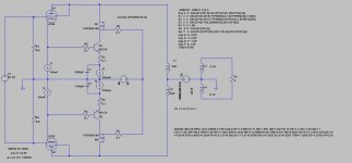
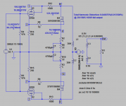
However, little is reported about the performance of super triode real world amplifiers, especially concepts that combine a triode with solid state decives. I simulated the following simplified concept with LT SPICE. It delivers 35W into 4 Ohm. I use a KT 88 in triode mode. The triode "sees" an almost infinite resistance. Hence it does not contribute to the output power but imprints its triode character on the circuit. Probably a 300B would be nicer, but I do not know whether it is a good idea to run a directly heated tube as a cathode follwer with the voltage swing across the entire heater circuitry.
The most crucial component in my approach is the cascoding mosfet. It creates a comfortable voltage range for the BD139 but has to to dissipate 50W each and stand around 1000V (voltage safety margins included). A suitable mosfet might be the IXFN36N100, at least in the simulation. The output transformer is a Lundahl LL1627 configuration C. A suitable power transformer would be the Lundahl LL1649. My intention is to run such an amp without any global feedback and only the triodes as local feedback devices.
Before considerung to built such an amp I would appreciate your critical comments and opinions.
All the best for 2016
KlausB
A new year is a good starting point for a new project. I read a lot on the internet about SUPERTRIODES where a triode is in a local feedback loop with a more efficient device such as a penthode, a BJT or a MOSFET. The aim is to achieve an audiophile triode characteristic plus a high current delivery capability.
Notes on Hiroshi Uda's STC Amplifiers
Super Triode connection Circuit (STC) Vacuum Tube Amplifier
Single-Ended Amplifiers & Super-Triodes
More Super-Triode Amplifiers
However, little is reported about the performance of super triode real world amplifiers, especially concepts that combine a triode with solid state decives. I simulated the following simplified concept with LT SPICE. It delivers 35W into 4 Ohm. I use a KT 88 in triode mode. The triode "sees" an almost infinite resistance. Hence it does not contribute to the output power but imprints its triode character on the circuit. Probably a 300B would be nicer, but I do not know whether it is a good idea to run a directly heated tube as a cathode follwer with the voltage swing across the entire heater circuitry.
The most crucial component in my approach is the cascoding mosfet. It creates a comfortable voltage range for the BD139 but has to to dissipate 50W each and stand around 1000V (voltage safety margins included). A suitable mosfet might be the IXFN36N100, at least in the simulation. The output transformer is a Lundahl LL1627 configuration C. A suitable power transformer would be the Lundahl LL1649. My intention is to run such an amp without any global feedback and only the triodes as local feedback devices.
Before considerung to built such an amp I would appreciate your critical comments and opinions.
All the best for 2016
KlausB
Attachments
I know nada (gar nichts) about spice simulations and other members will have to comment.
You can use DHTs as a cathode followers. A dedicated, center tapped, filament winding is needed for each bottle. Use the CT as the cathode connection point for all associated elements. Residual hum could be a problem, when 300Bs are employed. However, 2A3s should be OK. The "bulked up" 2A3 variants, such as the Sovtek and JJ, could be exactly what the Dr. ordered.
You can use DHTs as a cathode followers. A dedicated, center tapped, filament winding is needed for each bottle. Use the CT as the cathode connection point for all associated elements. Residual hum could be a problem, when 300Bs are employed. However, 2A3s should be OK. The "bulked up" 2A3 variants, such as the Sovtek and JJ, could be exactly what the Dr. ordered.
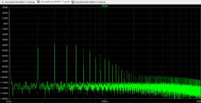
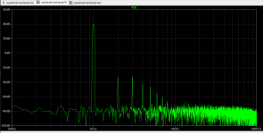
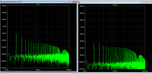
All even harmonics almost disappeared, added some GNFB, the odd one would be gone too. Probable still sound quite dry, compared to my OTL amp. So can try some other triode see what happened.
Attachments
Last edited:
All even harmonics almost disappeared, added some GNFB, the odd one would be gone too. Probable still sound quite dry, compared to my OTL amp. So can try some other triode see what happened.
Feed the setup with a resistively loaded 12AT7/ECC81 common cathode section that's outside any NFB loop. There's an excellent chance that the net distortion spectrum will be "better".
Feed the setup with a resistively loaded 12AT7/ECC81 common cathode section that's outside any NFB loop. There's an excellent chance that the net distortion spectrum will be "better".
Your're correct! This is 47k anode load 12AT7 @ 2mA, but the swing is limited to 5V input, anyway does it really emulating triode then?
Attachments
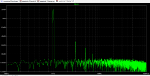
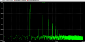
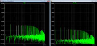
I added an anode/g2 load of 500 ohm on both tubes and monitor FFT on one side. The odd spectrum are looked alike and now reveal the original even harmonic level (this is higher level then output). So PP output has cancel even harmonic more than odd one in your design.
Attachments
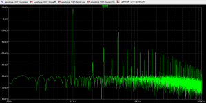
I have 2 more spectrum plots for 6c19p, and for comparing with my OTL amp, you can tell which one is closer. It appears totem pole type will preserve the harmonic better than balance PP transformer output
Attachments
Strapping 14 ohms across your relatively constant 0.7VBE
can give you the 50mA you need without a separate circuit.
Since you appear to have drawn cathode followers, I don't
see how a triode connection would be superior to pentode.
All the trouble to cascode your transistors, yet not use the
screen of the KT88 to similar purpose.
Perhaps bootstrap the screen to the cathode, or the emitter.
Last edited:
There was a long and detailed discussion of this showing that the idea is fundamentally flawed and will be a fairly high distortion design however you cut it.
long and detailed but well worth reading before sinking to much time into this idea:
Notes on Hiroshi Uda's STC Amplifiers
Shoog
long and detailed but well worth reading before sinking to much time into this idea:
Notes on Hiroshi Uda's STC Amplifiers
Shoog
Another version (inverted triode N Fdbk) (below) that is easier to understand than the STC:
http://www.diyaudio.com/forums/tubes-valves/20686-se-sound-p-p-amplifier.html
Distortion would depend on the gain device having enough forward gain to enforce compliance with the triode's reverse transfer function. Then it depends on that triode's linearity with CCS loading. Could be quite low distortion if done properly. The triode under CCS loading could be much more linear than the usual loaded SET configuration.
I have to agree with Tsugunari Eguchi in the linked thread. The incidental resemblance of the left side of the STC implementation to an SRPP is simply confusing the discussion. The input pentode is just acting as a current source signal injector. Anti-bootstrapping is not even seen by a high Zout 1st pentode.
I think Ross MacDonald (?) had a triode LTP circuit driving a pentode output, with the output (pentode) plate Negatively fedback back to one of the triode LTP plates, back in the 1950's. So this inverted triode feedback thing is not really new stuff. It just got re-invented a few times. TubeCad has it now too.
Changing the ground references around gives you the triode into SS Darlington (original poster's diagram) or the Sziklai compound pair (tube with P type Mosfet driven from plate). Each allows the triode tube's plate voltage (across the output) to act as N Fdbk.
Attachments
Last edited:
On second thought, I think it was F.E. Terman that had the inverted triode to LTP feedback circuit in one of his textbooks. Usually textbook stuff comes from some previously published paper anyway.
That STC circuit just needed a resistive attenuator between the output pentode plate and the feedback triode plate to fit the maximum voltage limits together better. Then more power output without distortion issues could have been obtained. The DC coupling also limited the biasing as well.
The STC circuit puts the input signal in on the feedback triode grid instead of the Op Amp (or LTP) + input shown for post #10 above.
Similarly for the above (post #10) Op Amp (or power amp) with triode feedback circuit, a resistor in series with the cap, from the amp output to the triode plate, can reduce the signal on the feedback triode to allow bigger output swings from the amp. Usually no voltage compliance problem with a SS amp and a triode tube for feedback (the reason not shown).
So nothing wrong with the basic inverse triode feedback concept, it just has to be implemented carefully. You can make a SS amp outperform a SET at its own game. And no SE OT needed. Or a P-P SS amp can be made to emulate a class A P-P tube amp using two inverted triodes. Another approach might be easier though:
http://www.diyaudio.com/forums/tubes-valves/75960-class-double.html#post871030
Like putting on tube veneer. It actually is equivalent to a class G or H amp. if the bigger amp is class AB and the smaller amp is class A.
Attachments
Last edited:
After revised thought:
It seems more important the MOSFET be 250mA.
Let triode bias fall wherever it may to achieve that.
Takes care of aging...
Just re-arranging parts you had already selected.
There are probably SICFETs better suited for this.
Less capacitance. More linear capacitance...
Check what CREE has to offer.
It seems more important the MOSFET be 250mA.
Let triode bias fall wherever it may to achieve that.
Takes care of aging...
Just re-arranging parts you had already selected.
There are probably SICFETs better suited for this.
Less capacitance. More linear capacitance...
Check what CREE has to offer.
Attachments
Last edited:
I have also described such a "tube enhancer", and an OTL application example:
http://www.diyaudio.com/forums/solid-state/235115-new-hybrid-concept-c-vac.html
http://www.diyaudio.com/forums/tubes-valves/235390-application-c-vac-solidglass-amplifier.html
http://www.diyaudio.com/forums/solid-state/235115-new-hybrid-concept-c-vac.html
http://www.diyaudio.com/forums/tubes-valves/235390-application-c-vac-solidglass-amplifier.html
@kenpeter:
i think we still need some bias resistor under the cathode. Assuming MOSFET Vgs threshold around 4V, the tube's cathode will be at approx 4.65V above ground, which consequently is also Vgk for the KT88. Vgk -4.6V for KT88 is way too high, i think?
More problem than just that, I shouldn't post things in my sleep.
Need to delete ALL my posts in this thread, wish I could. Havn't
gotten a single one right so far.
Last edited:
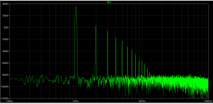
I added an anode/g2 load of 500 ohm on both tubes and monitor FFT on one side. The odd spectrum are looked alike and now reveal the original even harmonic level (this is higher level then output). So PP output has cancel even harmonic more than odd one in your design.
I now have simplified the sch, now adopted two slightly different anode loaded resistor (1.5K/1K). The harmonic of the output is surprisely similar to one of them (lower one)!
Attachments
Thank you everybody for your useful comments.
“Since you appear to have drawn cathode followers, I don't see how a triode connection would be superior to pentode.” Contrary to a BJT, j-FET, MOSFET, Tetrode or pentode the triode has the unique feature of an inherently built-in feedback, expressed by its low µ, i.e. the ratio of voltage change anode / grid at a given constant current. That seems to be the secrecy behind all STCs. In these designs the tube anode “sees” the full voltage swing at the primary transformer coils. The screen grid at a constant voltage would shield the anode from the voltage swing what, after all, is the purpose of a screen grid.
Hiroshi Uda’s design is limited to a very few watts. Another limitation that I got from the discussion is the small voltage swing of the feedback triode. Obviously high µ triodes are used as the discussion mentioned an internal resistance around 800k. I have no idea how Hiroshi’s amp sounds. However most real life speakers need more output power.
Furthermore I am not really convinced by tube SET designs, though I heard them a lot. The commercial solid state NPN / PNP push-pull designs need global feedback because of their inherently differing characteristics. That leaves MOSFET or BJT circlotrons (which indeed would be an alternative) or tubes. I own rather expensive speakers and I am afraid a DIY amp failure could burn out my voice coils or, even worse, my friends voice coils, because we swap our amps sometimes. An output transformer can be considered a life insurance for the speakers, just as a MC input transformer for expensive cartridges.
Kenpeter, I considered your design, it is close to the original from TUBECAD journal. Problem is that the triode control grid needs -27 volts @ 50mA idle and the power mosfets that can stand 1000V (including a safety margin if driven with speakers not connected) have either huge input capacitances (10nF to 15nF (!)) or low transconductance. The Miller effect would be a disaster. So the cascode with a grounded gate came to my mind and a low voltage BJT with high hfe around 100 to create a high “open loop” gain. I also thought about IGBTs but they seem to have a low reputation in audio.
Elvee, I like your approach. Basically you also use a triode as a cathode follower to drive a Sziklai pair through a current multiplier and feed-back the signal into the anodes.
Koonw, Lundahl recommends to not exceed the idle current above 350 mA for the transformer given. Otherwise power is limited mainly by the size of your heatsinks (wow, 100W triode class A). As far as I understand the resistors are lowering the voltage feedback into the triode, allowing a higher overall voltage swing across the transformer with an imbalance creating even harmonics.
Obviously the project is not completely maniac for your comments were quite positive. So I will carry on.
Regards
KlausB
IXCP10M90S is a depletion mode mosfet with relatively low capacitance and a 900V rating. It can be pass 100mA.
Also there are some very simple and very effective DC protection circuits which can be used with SS designs. They have saved my vintage drivers which have extreme sensitivity/delicacy. Really good SS amps with minimal global feedback are few but not difficult to find - any of the Nelson Pass First watt designs, a low power Le Monstre or even a well implemented JLH can match most valve amps.
Shoog
Thinking it over I found that the "supertriode" idea might be a good starting point for a single ended amplifier. Here is my concept:
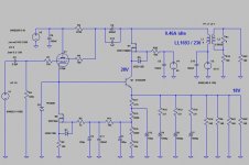
A KT66 power tetrode is a cathode follower and drives a 2SC5200 BJT. The current gain / collector current function of this BJT shows nice linearity and is a continuous function between 0.01A and 1.4A. The BJT is cascoded by a power MosFet. Contrary to the simulation an IXFN32N120 will work in the real life circuit for the MosFet has to take around 80W power loss. Furthermore the IXFN32N120 can stand voltage peaks up to 1.2kV. To be frankly I had no idea whether this industrial workhorse will perform well in an audio application.
The output signal at the MosFet drain is not fed back into the anode of a triode but into the screen grid of a KT66 power tetrode. This is different to the original "powertriode" concept but allows a decoupling of the anode current from the output transformer coils. For the anode current is almost constant it would just waste the transformer's headroom by magnetizing the core without contributing to power generation. For an appropriate function the KT66 needs around 300V at the anode while the solid state cascode works at 190V. Thus an electrolyte capacitor is unavoidable in the local feedback signal path.
The IRFP240 is the usual current sink to set the operation point of the KT66 to 60mA. Its gate senses the voltage drop at the BJT emitter and stabilizes the idle current of the 2SC5200 at 460mA. The primary coils of the Lundahl Lundahl 1693 (230mA) in parallel. Thus the primary inductance drops from 16H to 4H. The reflected primary impedance drops from 1000 Ohm to 250 Ohm.
The simulation delivers around 25W into 4Ohm. That should be sufficient to drive my Newtronics Temperance speakers. As a driver I will use an actively loaded 6SN7.
Attachments
- Status
- This old topic is closed. If you want to reopen this topic, contact a moderator using the "Report Post" button.
- Home
- Amplifiers
- Tubes / Valves
- SuperTriode with BJT and MosFet - a good idea?