ErikdeBest said:in Portuguese: Saúde a todos
Já agora tambem ía uma Caipirinha...!!

my goodness
I didn't know what I have started.....")
Anyway I have contacted mr. broskie (tubeCAD journal) with the same question.
His answer was something like this (I can not qoute so it will be copy/paste)
"Daniel,
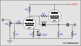
If you build the line amp you sent me, please add two resistor and one diode per channel. (picture is first one)
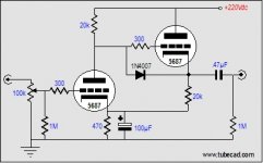
The 1-Meg resistors protect the power amp from seeing voltage spikes. If the pot loses contact, the grid will be left floating; if the output isn't terminated and if it saddenly does become terminated by the power amp, the power amp might see a 10-20volt spike that could damage it or the speakers. The diode protects the cathode follower at turn-on, when the full B+ voltage would otherwise be presented to the CF's grid, while its cathode was cold and at 0 volts. But I would not build the line amp; instead, I would build something like this picture is second one)
More current and less 100µF capacitor sonic contribution, as the 470-ohm cathode resistor sees a constant current flow, i.e. no AC signal, as the CF, while working in voltage phase with the grounded-cathode stage, works in anti-current phase with it. (picture is third one)
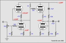
But if you are feeling adventurous, the following line amp has some nice features (4th one)
This circuit eliminates power-supply noise from the output, by injecting the same amount of PS noise at the bottom of the two-tube CF as the top of the CF sees; the result is that the noise cancels. One reader has built this circuit (except that he used 12AU7s) and he loves it.
John R. Broskie
I didn't know what I have started.....
Anyway I have contacted mr. broskie (tubeCAD journal) with the same question.
His answer was something like this (I can not qoute so it will be copy/paste)
"Daniel,
If you build the line amp you sent me, please add two resistor and one diode per channel. (picture is first one)
The 1-Meg resistors protect the power amp from seeing voltage spikes. If the pot loses contact, the grid will be left floating; if the output isn't terminated and if it saddenly does become terminated by the power amp, the power amp might see a 10-20volt spike that could damage it or the speakers. The diode protects the cathode follower at turn-on, when the full B+ voltage would otherwise be presented to the CF's grid, while its cathode was cold and at 0 volts. But I would not build the line amp; instead, I would build something like this picture is second one)
More current and less 100µF capacitor sonic contribution, as the 470-ohm cathode resistor sees a constant current flow, i.e. no AC signal, as the CF, while working in voltage phase with the grounded-cathode stage, works in anti-current phase with it. (picture is third one)
But if you are feeling adventurous, the following line amp has some nice features (4th one)
This circuit eliminates power-supply noise from the output, by injecting the same amount of PS noise at the bottom of the two-tube CF as the top of the CF sees; the result is that the noise cancels. One reader has built this circuit (except that he used 12AU7s) and he loves it.
John R. Broskie
Attachments
Hi,
Well, why not call the circuit by its' name?
The first stage is an SRPP direct coupled into a White CF....
As it hapens I already designed half a dozen of those fifteen years ago already and am currently working on one with the ECC99.
A circuit like that can drive the most ridiculous loads; low input impedance amps, headphones (including the notorious AKG 1000), hell even an efficient speaker.
Given a neutral sounding tube (a contradictio in terminis), the only sound you could possibly hear is the one from the passive components.
Have a go at it, you'll love it.
Cheers,
This circuit eliminates power-supply noise from the output, by injecting the same amount of PS noise at the bottom of the two-tube CF as the top of the CF sees; the result is that the noise cancels.
Well, why not call the circuit by its' name?
The first stage is an SRPP direct coupled into a White CF....
As it hapens I already designed half a dozen of those fifteen years ago already and am currently working on one with the ECC99.
A circuit like that can drive the most ridiculous loads; low input impedance amps, headphones (including the notorious AKG 1000), hell even an efficient speaker.
Given a neutral sounding tube (a contradictio in terminis), the only sound you could possibly hear is the one from the passive components.
Have a go at it, you'll love it.
Cheers,
That's not a White cathode follower. Its a normal cathode follower with a CCS load. A portion of the power supply noise is injected into the CCS such that it cancels any PS noise at the output.
A White cathode follower has a resistor above the top valve and the signal developed across this is fed to the lower valve.
A White cathode follower has a resistor above the top valve and the signal developed across this is fed to the lower valve.

- Status
- This old topic is closed. If you want to reopen this topic, contact a moderator using the "Report Post" button.
- Home
- Amplifiers
- Tubes / Valves
- AN7 prototype- variation?