Hi, is there any guide line for tube socket wiring to PCB?
I'm using a pre made PCB, but the chassis I have does not match up the holes with PCB mount sockets, hence I have to run fly wire to the PCB.
Should the heater wiring must be shielded from the rest (HT, grid, cathode ...)?
Max length of the wires (does the length reduce the sound quality)?
Wire type (24 x 0.2mm, 13 x 0.12mm)?
Thanks
Heater wiring should be tightly twisted, so that AC does not radiate into adjacent wiring.
Usually AC heater current doesn't go through PCB traces. Perhaps your PCB was designed for a DC heater supply.
It sounds like your PCB was made for a different tube socket than the ones you have. Why not find the correct PCB mount tube sockets for your PCB? They're usually inexpensive.
--
Usually AC heater current doesn't go through PCB traces. Perhaps your PCB was designed for a DC heater supply.
It sounds like your PCB was made for a different tube socket than the ones you have. Why not find the correct PCB mount tube sockets for your PCB? They're usually inexpensive.
--
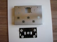
That looks like a Douk audio chassis for point to point wiring and the board looks like the one for their other chassis for EL34 output valves. Have you considered doing point to point wiring rather than use the circuit board? it is more flexible so makes component changes easier if you are wanting to upgrade or make modifications. Also helps learn how circuit works!
Thanks Avo, I have already traced the track vs the schematic.
My last tube amp built was 35+ years ago, hence my soldering would be considered as zero, therefore I want to use the PCB to minimise problem.
I'll be connecting the socket to the PCB hence want to know if there are problem when other cables are close to each other (apart from the burner wiring)?
My last tube amp built was 35+ years ago, hence my soldering would be considered as zero, therefore I want to use the PCB to minimise problem.
I'll be connecting the socket to the PCB hence want to know if there are problem when other cables are close to each other (apart from the burner wiring)?
There are a few things to consider, heater wiring does need to be kept separate and neatly twisted to reduce risk of hum pick up. Signal leads are prone to picking up noise so keeping them short is good. Also there are some components such as grid resistors that are best soldered direct to the valve socket as they are there to reduce RF into the valve so if they are portent in your schematic maybe solder direct to the socket and jumper the position on the board.
Things to think about if you have been away from soldering for a hole is that most solder supplied these days is lead free and bloody awful to work with! It is possible to get proper lead tin stuff if you try, I use solder that I have had in my toolbox for over 30 years. Also if using lead free stuff you need a recent soldering iron as it melts at a higher temperature than the old stuff.
Soldering is a bit like riding a bike once you have mastered it you will remember quickly how to do it. I tackled a point to point kit and, once I had decided where to put things, got it together pretty easily and then learned a lot trying to find the not very deliberate mistakes")
I guess using a PCB will make misplace,eng of components more difficult the risk of whiskers and dry joints on a PCB is some what higher if you are out of practice.
Best of luck with it I look forward to hearing how you get on.
Caber
Things to think about if you have been away from soldering for a hole is that most solder supplied these days is lead free and bloody awful to work with! It is possible to get proper lead tin stuff if you try, I use solder that I have had in my toolbox for over 30 years. Also if using lead free stuff you need a recent soldering iron as it melts at a higher temperature than the old stuff.
Soldering is a bit like riding a bike once you have mastered it you will remember quickly how to do it. I tackled a point to point kit and, once I had decided where to put things, got it together pretty easily and then learned a lot trying to find the not very deliberate mistakes
I guess using a PCB will make misplace,eng of components more difficult the risk of whiskers and dry joints on a PCB is some what higher if you are out of practice.
Best of luck with it I look forward to hearing how you get on.
Caber
- Status
- This old topic is closed. If you want to reopen this topic, contact a moderator using the "Report Post" button.
- Home
- Amplifiers
- Tubes / Valves
- Tube wiring guide line