Hi, I've google around on chassis earth and ground for tube amp and seems quite confusing in regards of ground loop.
My understanding is that chassis must always connected to Earth pin of the 240V input (AU standard) no exception.
Please clarify for me the followings:
Should the CT (0V) of 300V-0V-300V secondary be connected to the chassis? (I assume it should be yes)
Should the input (signal ground) also be connected to the chassis? (I believe the answer should be yes)
My understanding is that chassis must always connected to Earth pin of the 240V input (AU standard) no exception.
Should the CT (0V) of 300V-0V-300V secondary be connected to the chassis?
Should the input (signal ground) also be connected to the chassis?
These things used to be done in some equipment years ago. Now the approach is to have the entire circuit isolated from the chassis,
and then connect it to the chassis only with a single wire. Sometimes that wire connection includes a resistor and/or capacitor
and/or back to back high current diodes. The AC line safety ground is however always connected directly and immediately to the chassis.
There are special methods where it is not, but these are not suitable or safe for most home builders.
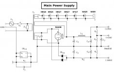
Here's how I designed the PS for a project I did. The whole PS is wired on a single circuit board with the rail voltages (+350, +150, -300, Neutral) coming off as independent leads with no connections to the chassis. Connections are led off to the various subsystems where required. The PS neutral is connected to a 50V/30A integrated bridge, as shown. It is also bypassed with a 10R/10W resistor to keep the connection if one or more diodes should poof if there's a line-to-ground fault. The 0.1uF capacitor serves to bypass high frequencies to ground. The earth connection is made directly to the chassis, and circuit ground through the ground loop breaker shown here. This serves to keep HV off the chassis, and doesn't cause the ground loop problems that using the chassis as a ground plane would tend to do.
Attachments
Here's how I designed the PS for a project I did. The whole PS is wired on a single circuit board with the rail voltages (+350, +150, -300, Neutral) coming off as independent leads with no connections to the chassis. Connections are led off to the various subsystems where required. The PS neutral is connected to a 50V/30A integrated bridge, as shown. It is also bypassed with a 10R/10W resistor to keep the connection if one or more diodes should poof if there's a line-to-ground fault. The 0.1uF capacitor serves to bypass high frequencies to ground. The earth connection is made directly to the chassis, and circuit ground through the ground loop breaker shown here. This serves to keep HV off the chassis, and doesn't cause the ground loop problems that using the chassis as a ground plane would tend to do.
Here's how I designed the PS for a project I did. The whole PS is wired on a single circuit board with the rail voltages (+350, +150, -300, Neutral) coming off as independent leads with no connections to the chassis. Connections are led off to the various subsystems where required. The PS neutral is connected to a 50V/30A integrated bridge, as shown. It is also bypassed with a 10R/10W resistor to keep the connection if one or more diodes should poof if there's a line-to-ground fault. The 0.1uF capacitor serves to bypass high frequencies to ground. The earth connection is made directly to the chassis, and circuit ground through the ground loop breaker shown here. This serves to keep HV off the chassis, and doesn't cause the ground loop problems that using the chassis as a ground plane would tend to do.
Hey Miles, thanks for the very clear description of your grounding scheme.
A question... Do you connect the audio circuits' 'ground' feeds to the "Neutral" bus as shown in your schematic?
Also, do you connect the CT from the heater winding directly to chassis as soon as possible, near the heater supply transformer?
--
You might find this useful - check out the grounding 101 document:
https://drive.google.com/folderview?id=0B_n67A1hN3qtfk5YYjY4WnlweUtwTFRMZ09GWTV4M0VlbXZnRkpHT1Ytdzk1LU96ZTZ4RU0&usp=drive_web
There are other aspects you need to consider in a power amplifier due to the relatively large currents involved but basically:
1. Mains input safety earth connects direct to chassis close to the mains input connector. This is mandatory from the safety point of view.
2. Use a copper bus bar for signal 0V through out the amplifier. Arrange connections to this bus so that output stages are at one end, drivers in the middle and inputs at the other end.
3. Connect the 0V from the HT supply to the high output stage end of this bus bar. The 0V of the HT is the the can of the last capacitor in the HT smoothing chain.
4. For unbalanced inputs (i.e. RCA) use insulated input sockets and connect the screen side to the bus bar at the input stage end.
5. If the heaters are centre tapped I generally connect the CT to the bus bar at the output stage end.
Hope that helps
Cheers
Ian
Thank you Rayma & Miles.
Do you have any guide line on the value of resistor and cap between the ground and chassis?
The connection from Audio to Chassis is there ONLY for safety. It is not there to help the amplifier towards better audio performance.I used a 10R/10W resistor, and a 0.1uF/150V capacitor for HF bypass.
That SAFETY connection from Audio to Chassis is to minimise the risk of someone touching a faulty component that has made some audio part LIVE due to some catastrophic failure inside or in a connected piece of equipment.
The SAFETY connection takes LIVE to Protective Earth via the Chassis. This route blows the Mains fuse very quickly if the impedance in the route is very low. This cannot be achieved, at mains frequency, with a resistor, nor with a capacitor.
The low impedance is achieved with a fat bit of copper wire. I have tested a power rectifier in lieu of this fat bit of copper and it passed my "test". Some here say that anything other than that fat bit of copper cannot comply with the regulations.
You have to decide whether to use copper, or a power rectifier, or as in some PASS diagrams use a Power Thermistor.
Go and read my test report if you want to research this, but do also read the regulation, if you can find it. I won't pay the £69 they charge here in the UK for the "book".
I consider this to be wrong.4. For unbalanced inputs (i.e. RCA) use insulated input sockets and connect the screen side to the bus bar at the input stage end.
The input via an unbalanced, or coaxial cable is a TWO WIRE connection.
That two wire connection must pass from the Source to the Receiver as a close coupled pair. That pair must form a continuous unbroken Flow and Return LOOP that has minimal LOOP AREA.
Taking the "ground" wire off to a different location somewhere else in the amplifier breaks that fundamental requirement of LOW LOOP AREA.
Hi, thanks everyone.
I found this http://www.valvewizard.co.uk/Grounding.pdf.
As I'm using a PCB for the tube amp, I'll isolate the PCB from chassis and connect only 1 point (the CT of the HT secondary from the power transformer) to the chassis.
I found this http://www.valvewizard.co.uk/Grounding.pdf.
As I'm using a PCB for the tube amp, I'll isolate the PCB from chassis and connect only 1 point (the CT of the HT secondary from the power transformer) to the chassis.
Don't connect the secondary CT straight to chassis. Lots of people do it, and lots of people are wrong to do it as it injects buzz straight into the ground connection. Instead, connect the CT to the negative of the first reservoir cap. Connect from there to any smoothing cap. From there to the signal ground (whether star or bus). From there to the chassis.
Note that old equipment from the 1950s may get this wrong. Back then they expected a little buzz with their music,
Note that old equipment from the 1950s may get this wrong. Back then they expected a little buzz with their music,
You might find this useful - check out the grounding 101 document:
https://drive.google.com/folderview?id=0B_n67A1hN3qtfk5YYjY4WnlweUtwTFRMZ09GWTV4M0VlbXZnRkpHT1Ytdzk1LU96ZTZ4RU0&usp=drive_web
There are other aspects you need to consider in a power amplifier due to the relatively large currents involved but basically:
1. Mains input safety earth connects direct to chassis close to the mains input connector. This is mandatory from the safety point of view.
2. Use a copper bus bar for signal 0V through out the amplifier. Arrange connections to this bus so that output stages are at one end, drivers in the middle and inputs at the other end.
3. Connect the 0V from the HT supply to the high output stage end of this bus bar. The 0V of the HT is the the can of the last capacitor in the HT smoothing chain.
4. For unbalanced inputs (i.e. RCA) use insulated input sockets and connect the screen side to the bus bar at the input stage end.
5. If the heaters are centre tapped I generally connect the CT to the bus bar at the output stage end.
All very clear, thanks, except for exactly where the bus bar is physically bonded to the metal chassis. Should this be done as close to the input *jacks* as possible? Or as close as possible to the input tube socket?
DF96 said:Don't connect the secondary CT straight to chassis. Lots of people do it, and lots of people are wrong to do it as it injects buzz straight into the ground connection. Instead, connect the CT to the negative of the first reservoir cap. Connect from there to any smoothing cap. From there to the signal ground (whether star or bus). From there to the chassis.
OK, thanks. That was the other part of the question I had. So everything 'floats' until it's bonded to chassis at the input.
I guess the idea is that the input stage, where signal magnitude is smallest, gets the lowest impedance path to the metal chassis 'ground.'
The output stage's path to ground, where signal magnitude is largest, goes through the longest length of (thick) wire to get to the metal chassis ground point.
Correct? If yes, then I am going to convert a badly humming amp I'm working on from a 1950s-style grounding scheme to this recommended grounding scheme and see if it makes a difference (fingers crossed). It will go:
120VAC green wire grounded to chassis at the power inlet (back of chassis).
Now from the front of the chassis:
- Ground post firmly attached to metal chassis near input stage tube sockets. Copper bus wire goes from there to back of amp. Copper bus wire is only connected to chassis at this one point at front of amp.
- Heater winding CT connects to bus wire at back of amp.
- HV secondary winding CT connects to bus wire at back of amp.
- Reservoir cap and first stage filter cap (CRC network) connect to bus wire near the HV winding CT.
- Ground leads from previous stages connect to bus wire working from back of amp to front of amp, until input stage ground leads go to bus wire at front of amp.
Like most circa-1960 integrated amps, this one has input jacks on the back panel, at the opposite end of the chassis from where the input stage and input selector/volume controls are. That means the input jacks will need a long ground wire going from the back of the chassis to the grounded end of the bus wire, at the front of the chassis. I assume that is preferable to grounding the input jacks where they're mounted to the chassis.
In my own layouts, I put the input jacks right next to the input selector switch and volume control. Then the input tubes are nearby, and have a short path to the post in the chassis where the ground bus connects. I don't have that choice in this project... and of course I'm having a hum problem.
Thanks for the help everybody.
--
On this last one I did, I didn't pay too much attention to physical locations (of the ground) and focused more on the actual order of the components grounding and how they connect. Quiet as a church mouse in a library. I could however be missing things so I'm interested to hear from the powers that be how much the physical location of the grounds matters.
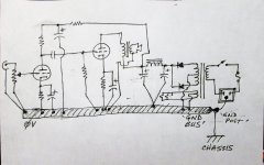
Here's how my last one was wired up:

Here's how my last one was wired up:
Last edited:
Here's how my last one was wired up:
The rectifier bridge is not drawn correctly. You may have it wired correctly, but the drawing does not match what you wired.
The rectifier bridge is not drawn correctly. You may have it wired correctly, but the drawing does not match what you wired.
Yeah i see i flipped one of the diodes in the anti-parallel bridge during my scribble. Its just the grounding network suggested in the Valve wizard paper is all.
No. You need to get away from thinking that 'ground' is some magic place when signals can be dumped. The chassis should not form part of the circuit at all.rongon said:I guess the idea is that the input stage, where signal magnitude is smallest, gets the lowest impedance path to the metal chassis 'ground.'
The output stage's path to ground, where signal magnitude is largest, goes through the longest length of (thick) wire to get to the metal chassis ground point.
No. You need to get away from thinking that 'ground' is some magic place when signals can be dumped. The chassis should not form part of the circuit at all.
OK. If the chassis is not part of the circuit, then why does the signal 0V bus need to be connected to chassis at all?
--
If the one and only 'ground' is coming from the green wire in the 3-prong AC connection (that's US color code, where green is Ground, white is Neutral, and black is Hot), then all I should need is a nice big ground bus wire going from where the green wire is secured to the back end of the chassis to the front of the chassis where the input wiring is.
If the layout is made so that...
- AC enters chassis at the rear, and green Ground wire is attached to chassis there,
- Power supply is at the rear,
- Output stage is next farthest from the rear,
- Driver stage is in the middle,
- Input stage is at the front,
then the ideal way to ground everything should be to put a stout bus from the AC socket, with the Ground conductively connected to chassis right there.
Then the bus goes from there to the front of the chassis, with the one and only conductive connection to chassis being back at the AC socket.
The transformer center taps are connected to the bus at the rear.
The power supply reservoir and decoupling caps connect just in front of those.
The output stage signal grounds connect to the bus just in front of the power supply.
The driver stage signal grounds connect next towards the front.
The input stage is at the end of the bus closest to the front of the chassis.
So the signal ground and power supply grounds are connecting to the actual Ground Post at the AC socket, which is where it all connects to the chassis.
If the chassis was made of non-conductive wood or plastic, would the grounding layout be the same?
--
PS -- The electrons have to flow from somewhere, so it makes sense to me if the green Ground wire from the AC cord turns out to be the source of all electrons flowing into the circuit. If that's not right, then I'm completely adrift in a sea of incomprehension...
--
Last edited:
The electrons have to flow from somewhere, so it makes sense to me if the green Ground wire from the AC cord turns out to be the source of all electrons flowing into the circuit. If that's not right, then I'm completely adrift in a sea of incomprehension...
--
That's not right either.
I really am adrift.
I consider this to be wrong.
The input via an unbalanced, or coaxial cable is a TWO WIRE connection.
That two wire connection must pass from the Source to the Receiver as a close coupled pair. That pair must form a continuous unbroken Flow and Return LOOP that has minimal LOOP AREA.
Taking the "ground" wire off to a different location somewhere else in the amplifier breaks that fundamental requirement of LOW LOOP AREA.
Nothing I said breaks this rule. it is sensible to locate the input sockets close to the input tube and hence to the end of the bus bar that the RCA screen needs to be connected. Connecting an unbalanced input direct to the chassis is definitely WRONG as it means interference currents can then flow in the signal 0V. The bus should be connected from the power end via a single wire to the chassis bolt that that also takes the safety earth to chassis. Making more than one connecting of signal 0V to chassis is a recipe for for disaster.
Cheers
Ian
OK, let's see if I'm following correctly. I've done a quick sketch of a two-stage SE amp with the power and output transformers, parts, and where I think everything should be grounded. It would be great if anyone could tell me if this is basically the right idea, or totally off. Thanks.
PS - What I labeled as 'GND POST' is the same as Ian's 'chassis bolt.'
PS - What I labeled as 'GND POST' is the same as Ian's 'chassis bolt.'
Attachments
Last edited:
- Status
- This old topic is closed. If you want to reopen this topic, contact a moderator using the "Report Post" button.
- Home
- Amplifiers
- Tubes / Valves
- Chassis earth and ground