With thanks to Mr. Bandersnatch...
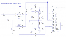
Here's a simple E-Linear style amp I'd like to try to shoehorn into a beater Dyna ST70 chassis. I have all the parts on hand, I won't have to buy anything (a major plus). Said chassis already has the four noval and five octal tube sockets installed for four 6P15P, four 6P3S and one 5AR4 rectifier. I've attached the schematic. I can upload the .asc file if people want to play with it.
According to the simulation, max power out should be 35W per channel. Distortion looks too-good-to-be-true, which is encouraging.
The 5AR4 might be replaced with a 5U4, if the B+ winds up being much higher than +420V. The reason I want the lower voltage is that I want this amp to use 6P3S output tubes (Russian '6L6GT') without burning them up. I like the way those tubes sound, they are still cheap, and I have some. I also have quite a few old Sylvania 6L6WGB I'd like to use if the amp turns out well.
The +420V B+ should put the 6L6 Va at +380V and Ia at 52mA, so the plate+screen dissipation will be almost exactly 20W. I know that will work with the old Sylvania 6L6's, and I'm hoping it will work with the Russian 6P3S's.
The CCS's will be made from a single DN2540 each, owing to space limitations.
The power supply will be a primitive CLC using the original teeny choke (1H 250mA) making a CLC of 47uF-1H-100uF. I don't know where I'd fit a bigger choke, so this will have to be it.
I know I'd get more power from fixed bias on the output stage. The original bias pots were removed and discarded long ago. I suppose I could put new ones in and restore the negative supply for fixed bias, which could also be used for the CCS supply. But then I'd have a much higher Va on the 6L6's and would have to use more expensive EL34's which I don't have, or re-think everything for pentode operation instead of UL. I'm not sure there would be room for a well-filtered or regulated screen supply.
Mr. Shoog and Mr. Wavebourne have talked me into trying 6P15P's for the LTP driver. It certainly looks good in simulation. Thanks to Shoog especially for patience and guidance.
If this design survives scrutiny, I'm looking forward to shoehorning it into my old ST70 and putting that old beater to good use.
Any thoughts? Improvements? Mistakes?
--
Attachments
Last edited:
Connection of U1/U2 plates )anodes) is really strange.
Why the are feed with HV not from B+ and resistor, but via sg1/s2 terminals of the output transformer?
It will work because of DC resistance of transformer winding is relatively small, but it will create feedback loop with unpredictable behaviour.
Why the are feed with HV not from B+ and resistor, but via sg1/s2 terminals of the output transformer?
It will work because of DC resistance of transformer winding is relatively small, but it will create feedback loop with unpredictable behaviour.
Connection of U1/U2 plates )anodes) is really strange.
Why the are feed with HV not from B+ and resistor, but via sg1/s2 terminals of the output transformer?
It will work because of DC resistance of transformer winding is relatively small, but it will create feedback loop with unpredictable behaviour.
The approach has been tested before and the feedback is exactly what the design is intended to achieve. Nothing to worry about.
Shoog
The approach has been tested before and the feedback is exactly what the design is intended to achieve. Nothing to worry about.
Shoog
Is there any article / post which describes how exactly it works, and the math behind it?
LinuksGuru,
Here: E-linear amplifier and Pete Millett's Apr. '05 article in AudioXpress.
Also Doug Piccard's e-linear posts here and on AA TubeDIY - Bandersnatch on DIYaudio and Packprotector on AA TubeDIY.
Here: E-linear amplifier and Pete Millett's Apr. '05 article in AudioXpress.
Also Doug Piccard's e-linear posts here and on AA TubeDIY - Bandersnatch on DIYaudio and Packprotector on AA TubeDIY.
Last edited:
Rongon,
Thanks for posting your project. I think I mentioned in another thread, which you started, about trying an amp like this with my ST-70 and using the 6P3S-E tubes but I had some problems with the driver pentodes being noisy and microphonic. I don't have any EL83's but I think I can round up a quad of EL-84's to try. I'd really like to see my amp succeed since I thought it had some good audio qualities. I installed an uprated power transformer so I've got plenty of current available.
John
LinuksGuru,
Here: E-linear amplifier and Pete Millett's Apr. '05 article in AudioXpress.
Also Doug Piccard's e-linear posts here and on AA TubeDIY - Bandersnatch on DIYaudio and Packprotector on AA TubeDIY.
OK, thanks, found some info on this interesting implementation.
This thread have it in details
http://www.diyaudio.com/forums/tubes-valves/149195-whats-advantage-e-linear.html
Thanks for all the replies...
Sure, I could see doing that. But is it necessary? The original circuit used four EL34's, which draw 1.5A each from their heaters (6A total) and the two 7199's draw 450mA each, so 6.9A total heater current. 6L6's draw 0.9A each, and 6P15P's draw 0.76A each, so that will be 6.64A total heater current for this circuit. That's actually less than the original circuit. I hear what you're saying, but I think I'd rather use whatever space there is to put in a bigger choke for the power supply.
Good question. The output tube's grid leak resistor is part of the feedback voltage divider. I wonder if increasing it will change anything. But yes, it would probably be a good idea to increase the value of the grid leak, if possible. I don't want to take it to the maximum, but 330k should be good.
Do you mean bias the 6P15P cathodes above ground? Otherwise, I don't get it. Also, how would I do that? Sorry, I'm not picturing it...
On a related topic, I was thinking that since this amp is not very sensitive, it may need a preamp-with-gain in front of it. If that's the case, then I have a line preamp with balanced outputs, ready to go. And if that's the case, then I can dispense with the negative supply, put a 150R 1W resistor from the LTP cathodes to ground, and make the amp usable with balanced input only. There are worse things.
--
Shoog said:If there is any room at all I would add another transformer for heater duty which should free up a bit of extra capacity to let those EL83's breath a little more.
A dinky little toroidal would take up minimal space.
Sure, I could see doing that. But is it necessary? The original circuit used four EL34's, which draw 1.5A each from their heaters (6A total) and the two 7199's draw 450mA each, so 6.9A total heater current. 6L6's draw 0.9A each, and 6P15P's draw 0.76A each, so that will be 6.64A total heater current for this circuit. That's actually less than the original circuit. I hear what you're saying, but I think I'd rather use whatever space there is to put in a bigger choke for the power supply.
ballpencil said:With autobias, 6L6GC spec sheet doesn't allow you to increase R8 and R9 to at least 220K?
Good question. The output tube's grid leak resistor is part of the feedback voltage divider. I wonder if increasing it will change anything. But yes, it would probably be a good idea to increase the value of the grid leak, if possible. I don't want to take it to the maximum, but 330k should be good.
ballpencil said:You can lose that -65V LTP bias voltage by biasing the grids above ground via B+ to GND voltage divider. You're using input coupling cap anyway. Less PSU headache.
Do you mean bias the 6P15P cathodes above ground? Otherwise, I don't get it. Also, how would I do that? Sorry, I'm not picturing it...
On a related topic, I was thinking that since this amp is not very sensitive, it may need a preamp-with-gain in front of it. If that's the case, then I have a line preamp with balanced outputs, ready to go. And if that's the case, then I can dispense with the negative supply, put a 150R 1W resistor from the LTP cathodes to ground, and make the amp usable with balanced input only. There are worse things.
--
Last edited:
Sure, I could see doing that. But is it necessary? The original circuit used four EL34's, which draw 1.5A each from their heaters (6A total) and the two 7199's draw 450mA each, so 6.9A total heater current. 6L6's draw 0.9A each, and 6P15P's draw 0.76A each, so that will be 6.64A total heater current for this circuit. That's actually less than the original circuit. I hear what you're saying, but I think I'd rather use whatever space there is to put in a bigger choke for the power supply.
My point is that the power that a transformer can deliver has two components. The amount of magnetism that thew core can sustain, and the wire resistance and hence heat induced sag.
By removing the heater from the main power transformer you have removed 42watts of load off the transformer which could potentially be transfered to the +B supply. It may not be realizable due to winding resistance and wire heating - but it could potentially free up 100mA of +B current.
Good question. The output tube's grid leak resistor is part of the feedback voltage divider. I wonder if increasing it will change anything. But yes, it would probably be a good idea to increase the value of the grid leak, if possible. I don't want to take it to the maximum, but 330k should be good.
In a recent modeling exercise I saw distortion fall when I reduced the grid leak resistors. Driving a relatively low grid leak resistor should be easy for the EL83. Also worth considering is the interaction with miller capacitance which is noted as the limiting factor with plate to plate feedback mentioned by Broskie in his article.
Shoog
Do you mean bias the 6P15P cathodes above ground? Otherwise, I don't get it. Also, how would I do that? Sorry, I'm not picturing it...
As it stands now, your cathodes sit 3.8V above ground. This is not enough for DN2540 to work if it terminates to ground (instead of -65V). Why don't we raise the grids to, say +12v so that now those cathodes sit at approx +15.8V. This is now enough for the DN2540. How do we raise the grids to +12V? Some options:
1. Use 12VDC for your heater supplies and connect your LTP grid leak resistors there. Cheap small SMPS do well here.
2. Voltage divider from your B+ to GND as i initially suggested. A 12V zener, bypass cap and a resistor from B+ will do. Then connect the grid leak resistors there.
Good points, both.
I see what you mean about the transformer, and I think you're right. Even when used with the stock circuit, the original Dyna PA060 transformer runs very hot. It would be a good thing to reduce the load as much as possible, and keep the heat down to reasonable levels. That's especially true when used within the cramped ST70 chassis.
I think I have some 6.3VCT transformers in the closet. I'll take a look to see if I have any rated at 3A that might fit in the chassis.
Another thing I could do is use solid state rectifiers instead of a rectifier tube, and save the current that would otherwise be used in the 5V heater supply. That, however, would raise the B+ up to about +460V, so the plate to cathode voltage on the output tubes would be about 410V (accounting for about 40V dropped across the cathode bias resistors). According to LTspice, that would raise 3rd harmonic distortion by 5dB at 1W output. I know better than to believe that LTspice is reporting distortion accurately on an absolute basis, but I want to suppress any trend toward higher levels of odd order distortions getting into the design. So in the interest of keeping 3rd HD as low as possible, I'll try to keep the B+ down to about 420V, probably using a 5AR4, or a 5U4 if necessary.
--
As it stands now, your cathodes sit 3.8V above ground. This is not enough for DN2540 to work if it terminates to ground (instead of -65V). Why don't we raise the grids to, say +12v so that now those cathodes sit at approx +15.8V. This is now enough for the DN2540. How do we raise the grids to +12V? Some options:
1. Use 12VDC for your heater supplies and connect your LTP grid leak resistors there. Cheap small SMPS do well here.
2. Voltage divider from your B+ to GND as i initially suggested. A 12V zener, bypass cap and a resistor from B+ will do. Then connect the grid leak resistors there.
I'm not sure I've seen those ideas put into practice, but they make sense. I threw #2 into LTspice, and it looks like it works fine. However...
How would global NFB be implemented with these arrangements?
--
The stock power transformer has a 70V winding already, which is what I plan to use for that -65V supply for the LTP tail.
--
Another question:
For the EL83 screen stoppers, R4 and R5, what value would be best used there? Does EL83 require fairly large value screen stoppers (1k or 2.2k ohms) to keep the screens from drawing too much current? Or are the screens usually stable with +150V, so only 100 ohms would be fine?
--
For the EL83 screen stoppers, R4 and R5, what value would be best used there? Does EL83 require fairly large value screen stoppers (1k or 2.2k ohms) to keep the screens from drawing too much current? Or are the screens usually stable with +150V, so only 100 ohms would be fine?
--
How would global NFB be implemented with these arrangements?
--
The stock power transformer has a 70V winding already, which is what I plan to use for that -65V supply for the LTP tail.
--
Yes, GNFB is not an option this way unless you add another DC blocking cap (which is not a good idea as it adds another pole) OR terminate the secondary to this +12V point, instead of GND. You schematic does not show any GNFB but it does show input coupling cap which means this idea is feasible. Recent post showed you might add separate transformer for heaters as well.. imo, this is a chance to DC supply the heaters (one less possible hum-inducing factor). Or use -12V for heater supply and connect the DN2540 there and you can still terminate the OPT secondary to ground and do the classic GNFB.
Yes, GNFB is not an option this way unless you add another DC blocking cap (which is not a good idea as it adds another pole) OR terminate the secondary to this +12V point, instead of GND. You schematic does not show any GNFB but it does show input coupling cap which means this idea is feasible. Recent post showed you might add separate transformer for heaters as well.. imo, this is a chance to DC supply the heaters (one less possible hum-inducing factor). Or use -12V for heater supply and connect the DN2540 there and you can still terminate the OPT secondary to ground and do the classic GNFB.
I'm hoping gNFB isn't necessary, but I'd like to keep the possibility of using it open.
Yes, it looks like I'm going to try to add a heater transformer. I'd rectify it, but that would mean more parts to fit into the chassis. I'm worried about the large electrolytic cap required, probably one or two 10,00uF 35V, or a 4700uF 35V cap and an LM338 regulator with heat sink. It's not complex, it will just be difficult to get it all stuffed into that cramped chassis.
At any rate, it looks like the basic circuit is meeting with approval, so I'll carry on. I won't be able to get to it tomorrow, but maybe I can start in on it Monday.
--
I'm thinking of losing the input cap. It's there to relieve the output stage of boosting frequencies around 10Hz to make up for losses at its grids. Fitting a 0.22uF cap with 100k grid leak on the input flattens out the response at the 6L6 plates. Why this is happening is beyond me, but I can see it in the LTspice virtual 'scope.
--
Last edited:
A question:
What is the acceptable range of screen voltage for an EL83 with about 200V on its plate? Do I want the screen voltage to be as high as possible, but less than the plate voltage?
The data sheets show curves with 170V on the screen. They also show the max Vg2 as 300V (that's a surprise), with max Pg2 = 2W. So that would be Vg2 of 300V with Ig2 of 6.5mA.
I've been aiming for Va = 200V, Vg2 = 150V. Is that optimal, or is Vg2 = 100V or 120V just as good?
EL83 Ra is 27k4.
--
- Status
- This old topic is closed. If you want to reopen this topic, contact a moderator using the "Report Post" button.
- Home
- Amplifiers
- Tubes / Valves
- Proposed E-Linear PP 6L6GB w/ EL83 LTP - Critique?