Hi folks,
I'm an electronics novice building an ST70-ish home brew amp. I would like to be able to use various input sources, including SS preamp line out, as well as headphone output from a laptop / tablet / smart phone. Would there be a problem in hooking these up directly? Or should I change the input resistor from the traditional 470K in order to present a better input impedance? If I did that, what impact would it have with regard to the grid-to-cathode reference for the input stage? Or maybe I need a buffer of some sort?
Been lurking here a long time, learning lots. Thanks guys.
Dave
Stop fretting! ") A problem occurs when then I/P impedance of the downstream unit is too low. Waveform fidelity is preserved, when the O/P impedance of the driving unit is low and the I/P impedance of the driven unit is high.
A problem occurs when then I/P impedance of the downstream unit is too low. Waveform fidelity is preserved, when the O/P impedance of the driving unit is low and the I/P impedance of the driven unit is high.
Close matching of impedances is needed, for max. power transfer. You are dealing with a small signal situation.
BTW, an IHF "standard" requires a SS preamp be capable of driving a power amp whose I/P impedance is 10 Kohms. The 470 Kohm I/P impedance of a ST70 is "a piece of cake".
A problem occurs when then I/P impedance of the downstream unit is too low. Waveform fidelity is preserved, when the O/P impedance of the driving unit is low and the I/P impedance of the driven unit is high.Close matching of impedances is needed, for max. power transfer. You are dealing with a small signal situation.
BTW, an IHF "standard" requires a SS preamp be capable of driving a power amp whose I/P impedance is 10 Kohms. The 470 Kohm I/P impedance of a ST70 is "a piece of cake".
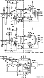
All the sources input should be properly terminated into their correct impedance. A headphone output from pc/laptop will have 16-600 ohms, you can terminate it with a 600 ohms resistor before it is connected to your amp, But it is likely to have hum and noise from computer switching and audio transformer is only way to remove them. Since you have many sources your should use a selector switch and each correctly terminated. Attached is Dynaco st70 sch, and you can see there is a 10 ohms resistor acting as ground lift, which should improve the ground loop hums and noise. You also need to experiment with high quality interconnect if you experience hums and hiss rather than change the amp gain design which can make it worse than you begin with. The high impedance of ST70 is fine, it can take input from almost any low source.So as I'm using a basic high gain pentode (EF86) input stage, and assuming I'll be driving it with a headphone level signal, what should I do for the input resistor value? Or should I just go with a lower gain input stage?
Dave
Sometimes you need to add ground lift to input amp if you don't use audio isolation transformer.
Attachments
All the sources input should be properly terminated into their correct impedance. A headphone output from pc/laptop will have 16-600 ohms, you can terminate it with a 600 ohms resistor before it is connected to your amp, But it is likely to have hum and noise from computer switching and audio transformer is only way to remove them. Since you have many sources your should use a selector switch and each correctly terminated. Attached is Dynaco st70 sch, and you can see there is a 10 ohms resistor acting as ground lift, which should improve the ground loop hums and noise. You also need to experiment with high quality interconnect if you experience hums and hiss rather than change the amp gain design which can make it worse than you begin with. The high impedance of ST70 is fine, it can take input from almost any low source.
Sometimes you need to add ground lift to input amp if you don't use audio isolation transformer.
I was actually wondering about the 470K resistors across the inputs. Does this set the input impedance? Is that the same as "terminating it" like you mentioned above. Sorry for these stupid questions. I have no training in electronics other than what I am able to get from sites like this one.
Dave
Hi folks,
I'm an electronics novice building an ST70-ish home brew amp. I would like to be able to use various input sources, including SS preamp line out, as well as headphone output from a laptop / tablet / smart phone. Would there be a problem in hooking these up directly? Or should I change the input resistor from the traditional 470K in order to present a better input impedance? If I did that, what impact would it have with regard to the grid-to-cathode reference for the input stage? Or maybe I need a buffer of some sort?
Been lurking here a long time, learning lots. Thanks guys.
Dave
You only need to be concerned with inout impedance matching with RF circuits. At audio frequencies, the input impedance is equal to the value of the DC grid return resistor, which you mention: 470K. The only problem you'd encounter is if the Zo was comparable to that value that would form a voltage divider. None of the devices you mention here should pose any sort of problems.
About the only thing that might pose such a problem would be an unbuffered, hollow state pre. Some such designs do exist.
I was actually wondering about the 470K resistors across the inputs. Does this set the input impedance? Is that the same as "terminating it" like you mentioned above. Sorry for these stupid questions. I have no training in electronics other than what I am able to get from sites like this one.
Dave
Yes it almost will set the input impedance, as the actual input impedance is this resistor in parallel with input impedance of the active device. The resistor is set by design of amp the chosen value has to take grid leak bias into and input source into consideration, you may change it to lower value but not necessarily higher than design as it will disturb the operation, usually 1M the upper limit and 10K the lower limit.
When you connect the headphones to laptop you effectively terminated it correctly if you hear clear and undistorted sound, and it's this terminated condition give you the best sound input to your amp. So you see now 600 ohms termination and 470K they are separate functions even though they are connected together.
I would load something like a laptop or iphne with something like 10K if it is a headphone output. They could have startup offsets when loaded with rather high impedance. The coupling cap could take a while to charge.
I ran a ST 70 sirectly connected to a PC for quite a while. The souns was good and I did not exnounter any hum problems.
I ran a ST 70 sirectly connected to a PC for quite a while. The souns was good and I did not exnounter any hum problems.
Yes it almost will set the input impedance, as the actual input impedance is this resistor in parallel with input impedance of the active device. The resistor is set by design of amp the chosen value has to take grid leak bias into and input source into consideration, you may change it to lower value but not necessarily higher than design as it will disturb the operation, usually 1M the upper limit and 10K the lower limit.
When you connect the headphones to laptop you effectively terminated it correctly if you hear clear and undistorted sound, and it's this terminated condition give you the best sound input to your amp. So you see now 600 ohms termination and 470K they are separate functions even though they are connected together.
Isn't the input-to-ground resistor (470K in the ST70) also for setting the input tube bias due to its relationship to the cathode-to-ground resistor? In that case wouldn't I be screwing up the bias if I changed the input resistor without changing the cathode resistor proportionally? Would this then mess up the relationship of the cathode resistor to the anode resistor, and maybe the voltage to the next stage?
Thanks in advance for the help. Obviously I know just enough to be dangerous.
No, not at all. It does not determine any of that. All it does is a give a path from grid to ground, and give something to the previous device to "bite on". So all the other components around the input stay the same, except if you have an input capacitor. In that case, as the resistor goes low, the capacitor goes high in value to keep the same bass roll-off freq.
Isn't the input-to-ground resistor (470K in the ST70) also for setting the input tube bias due to its relationship to the cathode-to-ground resistor? In that case wouldn't I be screwing up the bias if I changed the input resistor without changing the cathode resistor proportionally? Would this then mess up the relationship of the cathode resistor to the anode resistor, and maybe the voltage to the next stage?
Thanks in advance for the help. Obviously I know just enough to be dangerous.
Grid bias resistor is referenced to ground in the cathode bias method, it will not affect the bias voltage if it is below the upper limit, the lower limit can be zero if not use for input. The bias voltage is solely derived from potential difference in grid and cathode as the current flows in cathode resistor. A change in bias resistor value therefore will not change the bias voltage. The bias resistor has effect on the frequency respond however.
There is another method of bias called grid leak bias or contact bias, the bias voltage is derived differently from cathode bias, change of bias resistor will change the bias voltage.
- Status
- This old topic is closed. If you want to reopen this topic, contact a moderator using the "Report Post" button.
- Home
- Amplifiers
- Tubes / Valves
- Help with input impedance