Dear folks,
I know, there are a lot of RIAA preamps arround and most of them are quite "better" than the solution I would like to build. But start with" simple" things is better (and cheeper) than build a high-end which cost horrobil mony and don´t work

So I decided to build a preamp which Eli show here:
http://www.diyaudio.com/forums/tubes-valves/280674-12ax7-phono-preamplifier.html
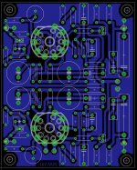
I routed a small PCB with two channels and it works so far. A little humm for which I have work on ( other routing ?? )
Questions:
1) I do not understand the 20M resistor at grid of second triode. Spice simulations shows no difference if I use a standart 1M grid leak resistor instead.
2) Measure the output with open input ( no cable attached to PCB ) I measure some hum but also a random DC level which move +/- 200mV. At one channel I measured +/-400mv so I changed the tube. It´s better now but I wonder what is the reason for this fluctuation??
3) Routing the PCB to get as best as possible hum free output is the major nightmare on all my projects. So I decide to use 12V DC for heaters and big ground areas. Does a star grounding make sens on PCB if I already use ground areas ( possible double sided PCB )?
Thanks a lot for any hint.
Best regards
Karsten
I know, there are a lot of RIAA preamps arround and most of them are quite "better" than the solution I would like to build. But start with" simple" things is better (and cheeper) than build a high-end which cost horrobil mony and don´t work
So I decided to build a preamp which Eli show here:
http://www.diyaudio.com/forums/tubes-valves/280674-12ax7-phono-preamplifier.html
I routed a small PCB with two channels and it works so far. A little humm for which I have work on ( other routing ?? )
Questions:
1) I do not understand the 20M resistor at grid of second triode. Spice simulations shows no difference if I use a standart 1M grid leak resistor instead.
2) Measure the output with open input ( no cable attached to PCB ) I measure some hum but also a random DC level which move +/- 200mV. At one channel I measured +/-400mv so I changed the tube. It´s better now but I wonder what is the reason for this fluctuation??
3) Routing the PCB to get as best as possible hum free output is the major nightmare on all my projects. So I decide to use 12V DC for heaters and big ground areas. Does a star grounding make sens on PCB if I already use ground areas ( possible double sided PCB )?
Thanks a lot for any hint.
Best regards
Karsten
Attachments
If your simulation shows no difference between 1M and 20M grid leak resistor then this means that the triode model does not correctly do grid current.karsten21 said:I do not understand the 20M resistor at grid of second triode. Spice simulations shows no difference if I use a standart 1M grid leak resistor instead.
Hello DF96,
Yes might be that the used spice model does not implement complete grid current. But in fact this does not enlight me concerning how a 20Meg resistor has to be set as grid leak resistor.
Do you have any explanation for this..please ?
EDIT:
Aiieee: Did the schematic use a grid bias using the 20Meg and the few micro Amp from Grid current to bias the tube?
It seemed to me correct but... I read that this way of biasing a tube is not preditcable and therefor should not to be used.
The issue now is: I can change this to a "normal" kathode biasing but how to measure the used bias voltage? A normal multimeter has 10Meg as input resistance... measureing on a 20Mge weill return... soemthing...
Sorry for editing...
Karsten
Thanks a lot
Karsten
Last edited:
Measure the anode voltage. Then use 'normal' bias and adjust until you get the same anode voltage. I would just use a red LED though.I can change this to a "normal" kathode biasing but how to measure the used bias voltage?
DF96 is right.
Karsten21, try with this Nakabayashi model for 12AX7, works good in LTspice.
*
* Generic triode model: 12AX7
* Copyright 2003--2008 by Ayumi Nakabayashi, All rights reserved.
* Version 3.10, Generated on Sat Mar 8 22:41:09 2008
* Plate
* | Grid
* | | Cathode
* | | |
.SUBCKT 12AX7_AN A G K
BGG GG 0 V=V(G,K)+0.59836683
BM1 M1 0 V=(0.0017172334*(URAMP(V(A,K))+1e-10))**-0.2685074
BM2 M2 0 V=(0.84817287*(URAMP(V(GG)+URAMP(V(A,K))/88.413802)+1e-10))**1.7685074
BP P 0 V=0.001130216*(URAMP(V(GG)+URAMP(V(A,K))/104.24031)+1e-10)**1.5
BIK IK 0 V=U(V(GG))*V(P)+(1-U(V(GG)))*0.00071211506*V(M1)*V(M2)
BIG IG 0 V=0.000565108*URAMP(V(G,K))**1.5*(URAMP(V(G,K))/(URAMP(V(A,K))+URAMP(V(G,K)))*1.2+0.4)
BIAK A K I=URAMP(V(IK,IG)-URAMP(V(IK,IG)-(0.00058141055*URAMP(V(A,K))**1.5)))+1e-10*V(A,K)
BIGK G K I=V(IG)
* CAPS
CGA G A 1.7p
CGK G K 1.6p
CAK A K 0.5p
.ENDS
1) I do not understand the 20M resistor at grid of second triode. Spice simulations shows no difference if I use a standart 1M grid leak resistor instead.
I've modeled both Eli's RIAA and Thorsten Loesch's 'El Cheapo' RIAA (ECC83 to ECC88). Both use grid leak bias (aka contact potential bias) on the second stage.
The Ayumi 12AX7 model that RajkoM posted is the one I use. I find it still doesn't model grid current correctly, so grid leak bias doesn't work well with it.
The idea behind using grid leak bias is that you can put a mammoth resistance loading the first stage and EQ (20M ohms). The bass EQ will work much better that way.
If you're worried about it, maybe you could make your PCB with pads for a cathode resistor and cathode bypass capacitor for the second stage, and simply short them between the tube's cathode and ground to try out grid leak bias with the 20M resistor. If that doesn't work for you, you can change the value of the grid leak to something like 510k or 1M, take out your jumper wires, and install your cathode resistor and bypass cap (or an Infrared LED, or whatever). You'll also have to change some values in the EQ if you put in a cathode resistor.
--
What happens if you put a 1 ohm cathode resistor in your simulation? You should see maybe 0.001V across that resistor, which would indicate 1mA being drawn through the second stage 12AX7.
--
Last edited:
The original reason for grid leak bias is that it allows the cathode to be directly grounded. This means that noise from AC heater-cathode leakage is grounded too; a direct connection will always have lower impedance than a bypass capacitor. Useful for low noise input stages.
Grid leak, AKA contact, bias works well only in low signal level situations. A phono preamp is a low signal level situation. ") As previously stated, the huge grid leak resistor lightly loads the EQ network, which improves bass extension. Thorsten Loesch originated the concept.
As previously stated, the huge grid leak resistor lightly loads the EQ network, which improves bass extension. Thorsten Loesch originated the concept.
FWIW, something on the order of 2 V. of bias should be found, when the 20 Mohm resistor is employed.
While computer simulations can be beneficial, only cut and try yields fact(s).
As previously stated, the huge grid leak resistor lightly loads the EQ network, which improves bass extension. Thorsten Loesch originated the concept.FWIW, something on the order of 2 V. of bias should be found, when the 20 Mohm resistor is employed.
While computer simulations can be beneficial, only cut and try yields fact(s).
While computer simulations can be beneficial, only cut and try yields fact(s).
Amen to that!
the huge grid leak resistor lightly loads the EQ network, which improves bass extension.
The RIAA bass roll off is set by the coupling capacitor and the DC load after it.
A 1M grid resistor and 0.1uF cap (1.6Hz) would be fine. No need for 20M in this respect.
Last edited:
Regarding hum, in building this circuit I found it important to ground the regulated 200 VDC B+ and the heater supply together and direct them straight to the chassis earth, keeping a separate star grounding scheme for the signal.
AC power routing is important in this design. I had started to use a low-current 120VAC pilot light for the chassis, and just bringing the wiring near the circuit caused low level hum. I ended up switching to a 12VDC LED pilot, pulled from the heater supply. No hum. Keeping all mains wiring to the transformer well away from the board should help some, too.
AC power routing is important in this design. I had started to use a low-current 120VAC pilot light for the chassis, and just bringing the wiring near the circuit caused low level hum. I ended up switching to a 12VDC LED pilot, pulled from the heater supply. No hum. Keeping all mains wiring to the transformer well away from the board should help some, too.
Dear guys,
Thank you all for your input. It´s always a pleasure for me to read this forum. All these experts and no bad word for simple questions. Thanks a lot!
I measured Ua= 138V at the second triode. Using Ra=100K and 230V as supply voltage at this point I can draw the resulted load line. I wrote some grid curves using the uTracer from Ronald Dekker ( by the way: The best valve tracer I know! ) of the used ECC803 from JJ. The result is a bias of ~ -0.8V.
For that a LED can´t be used here. As I use a DC heater voltage of 12V it´s not necessary to ground the cathode to prevent hum.
I will play a little bit using a "normal" resistor for cathode biasing instead grid biasing because 20Meg resistors are a little bit rare. Furthermore I´would like to bias the tubes at a more stable and predictable point.
I build a small alu-case and find out, that without this case the hum is significant. On next PCB version I will use a star grounding for signals on bottom layer and heater voltage on top. The rest of the top layer will be routed as ground plane.
Thanks for your help!
Regards
Karsten
Attachments
I hate doing this, particularly regarding a design by Eli, who I hold in great esteem, but .....
As I understand, the grid-leak bias is not only generated by contact bias, but a few electrons 'hitting' it during positive swings also contribute. It is thus a kind of auto-bias, always keeping the operating point somewhat more optimal than 'fixed' cathode bias.
Data and measurements show though, that the input impedance is thus lower than the grid resistor (20M) itself, because of some (though minute) current drawn by the grid. Furthermore (and because of this) distortion can become high unless fed from a low impedance source. Unfortunately the preceeding RIAA network is not low-Z.
The exact bias is difficult to measure. As Merlinb suggested, it is easiest determined by using a low grid resistor and adjusting cathode bias to give the same anode voltage, then measuring the resulting cathode voltage.
Also, I have used it not only for very low input signals, as e.g. an input stage for a power amplifier. Though input stage distortion is unimportant in power amplifiers, I found the 'grid-leak' bias to give lower distortion than cathode bias, when fed from a low impedance source (a cathode follower in my case). RCA data sheets for 12AX7 give examples of typical distortion, perhaps other brands also do.
Slightly OT then, but thought I would add this as a marginal note.
Johan,
So far, everybody that's built the tweaked RCA setup has been satisfied. I went to grid leak bias, based on Thorsten Lösch's experience and recommendation. The MOSFET buffer is, pretty much, a no brainer.
For those who want more gain, CCS loading the grid leak biased 2nd gain block at 900 to 1000 μA. is (IMO) the way to go. CCS loading the cathode biased 1st gain block could adversely impact on RIAA EQ performance.
So far, everybody that's built the tweaked RCA setup has been satisfied.
I went to grid leak bias, based on Thorsten Lösch's experience and recommendation. The MOSFET buffer is, pretty much, a no brainer.For those who want more gain, CCS loading the grid leak biased 2nd gain block at 900 to 1000 μA. is (IMO) the way to go. CCS loading the cathode biased 1st gain block could adversely impact on RIAA EQ performance.
Johan,
So far, everybody that's built the tweaked RCA setup has been satisfied.
For those who want more gain, CCS loading the grid leak biased 2nd gain block at 900 to 1000 μA. is (IMO) the way to go. CCS loading the cathode biased 1st gain block could adversely impact on RIAA EQ performance.
Has anyone who built actually measure the distortion for comparison? It appears the distortion is higher than cathode bias, but also appears that most people can tolerate this kind of distortion.
I have reading material to back up #14. SERIES GRID-LEAK BIAS
You can read page 33 - 35, I believe it is shunt grid leak type, which required a capacitor Cc (which one?) and resistor Rg.
"The extent of the bias on the grid will depend on three things: the amplitude of the input, the frequency of the input, and the size of Rg and Cc. This type of biasing has the advantage of being directly related to the amplitude of the input signal. If the amplitude increases, biasing increases in step with it. The main limiting factor is the amount of distortion that you may be willing to tolerate. Distortion occurs during the positive alternation when the grid draws current. Current drawn from the electron stream by the grid never reaches the plate; therefore the negative-going output is not a faithful reproduction of the input, while the positive-going output (during the negative input cycle) will be a faithful reproduction of the input. This is similar to the situation shown in the flattopped portion of the output signal in figure 1-20."
I think equilibrium is being overlooked. At power on, the grid carries no charge. Some of the thermionic electrons strike the grid. They bleed off to ground, via the grid to ground resistor. The large value of the resistance slows the bleeding down. An equilibrium between electrons hitting the grid and bleeding off is established.
The contact potential, with a 20 Mohm resistor, is about 2 V. Even with the slight variation that inevitably occurs, the small signal level being handled is dealt with in a linear manner. AFAIK, the best places to employ contact bias are in phono sections and grid leak AM envelope detectors. L_RD knows that I used my share of 2.2 Mohm resistors in parallel with 250 pF. caps., as a youngster in AM radios.
The contact potential, with a 20 Mohm resistor, is about 2 V. Even with the slight variation that inevitably occurs, the small signal level being handled is dealt with in a linear manner. AFAIK, the best places to employ contact bias are in phono sections and grid leak AM envelope detectors. L_RD knows that I used my share of 2.2 Mohm resistors in parallel with 250 pF. caps., as a youngster in AM radios.
Johan,
So far, everybody that's built the tweaked RCA setup has been satisfied.
For those who want more gain, CCS loading the grid leak biased 2nd gain block at 900 to 1000 μA. is (IMO) the way to go. CCS loading the cathode biased 1st gain block could adversely impact on RIAA EQ performance.
Eli...no everybody.I tried it (the FET tweak for low the out Z) and don´t like its sound, at my taste of course. The hights are gonne.Puzzling, because the input capacity gate is in theory, very, very low. I don´t know why.
Now it works fine (no FET) like a "RCA Classic". Only with led´s mods in cathodes.A IR for the first, and a vulgar red one in the second.
The out Z is yet too hight.It must load at 250 Kohm min.
Cheers
Hey Folks,
Unfortunately I crashed my soundcard input for that I´m not able to measure RIAA curve or spectrum. I have to wait until I get a new (hopfully better) one.
Related to Family and Christmas I can´t spent enought time in my labor to work on the second triode biasing.
I come back with results as fast as possible...
Thanks a lot for your input!
Regards
Karsten
- Status
- This old topic is closed. If you want to reopen this topic, contact a moderator using the "Report Post" button.
- Home
- Amplifiers
- Tubes / Valves
- Classi RIAA preamp questions