Hego, did you use the ZVN0545A MOSFET called for? FETs with large reverse transfer capacitance roll HF information off.
What Eli said! I've used the ZVN0545A in a couple different preamp circuits and the results have been EXTREMELY good.
The higher the current through the ZVN0545A the higher the Gm too. So I ran it at about 3.5 ma. with 115 or so volts on the source.
Try that circuit again with that specific MOSFET and see if you don't get better results.
Hego, did you use the ZVN0545A MOSFET called for? FETs with large reverse transfer capacitance roll HF information off.
Yes, I used it.
Is rare because the capacity by Miller effect from the grid of 12ax7 is huger as the gate of ZVN0545A, and the gain is under 1: minimal Miller effect.
Repeat: I don´t know why.
Cheers
Chris
Hello folks,
Sorry to dig out this thread.
First of all: The RIAA preamp works and sounds very fine now. Unfortunately it hast to much gain! I measure 45dB@1Khz and want to have only 40dB. I tried some other tubes (JJ Ecc83S, JJ ECC803S, Sovtek 12AX7LPS, Shuguang 12AX7B ) but there is only negligible difference.
The big question now is: How to reduce the over all gain to 40dB@1Khz without to hit the RIAA EQ?
I try to use a feedback resistor from C6/R9 to gate of first stage. This seemed to work but the low fequencies are dropped down ( if I can trust LTSpice simulation ). To reduce noise it make sense to reduce gain on first stage..
Any idea?
Thanks a lot,
Karsten
Attachments
To reduce noise it make sense to reduce gain on first stage.
For the lowest noise, you need to have high gain in the first stage.
In any event, in this circuit you need as much gain as possible in both stages.
To change the midband gain and retain accuracy, the RIAA network must be redesigned.
Last edited:
Hello folks,
Sorry to dig out this thread.
First of all: The RIAA preamp works and sounds very fine now. Unfortunately it hast to much gain! I measure 45dB@1Khz and want to have only 40dB. I tried some other tubes (JJ Ecc83S, JJ ECC803S, Sovtek 12AX7LPS, Shuguang 12AX7B ) but there is only negligible difference.
The big question now is: How to reduce the over all gain to 40dB@1Khz without to hit the RIAA EQ?
I try to use a feedback resistor from C6/R9 to gate of first stage. This seemed to work but the low fequencies are dropped down ( if I can trust LTSpice simulation ). To reduce noise it make sense to reduce gain on first stage..
Any idea?
Thanks a lot,
Karsten
If you can find them, you can try 5751 (old GE 5-star tube) which has mu of 70 instead of mu of 100.
What's wrong with 45dB of gain? What cartridge are you using? Maybe your cartridge has higher gain than most.
--
Hello everyone,
I am an unconditional power triode is my Blogg: Officina Tron-audio Switzerland
you will find a section with DIY describing a multitude module dedicated to audio.
as here for a map RIAA Phono MM / MC dedicated: Officina Tron-audio Switzerland: Préamplificateur Phono MM/MC
or here (under construction) with the description of an optimized phono Marantz replica card: Officina Tron-audio Switzerland: Préamplificateur phono MM Marantz Replica
I let you watch and read and if you want more information you can contact me via blogg or so more directly here: antony.turchi@tron-audio.ch
Best regards. Tony
Dear Koonw
Thanks a lot and bow down!
I do not add the both capacitors in simulation because I thought it´s not relevant for simulating.
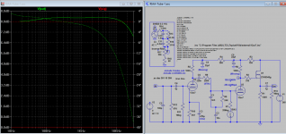
Increasing the kathode bypas capacitor to 470µ will improve the bass response up to 0.5dB wich is quite linear after this modification.
I played a little bit with bias of the second system and set it now to 1.33V using a kathode resistor of 1K9 and a bypass capacitor of 1n8 to improve high frequencies between 10Khz and 20Khz.
Now it looks very linear and has an over all gain of 39.8dB which is more than exact for me. Now lets move the simulation to reality...")
Thanks a lot for your simulation modification especial the reverse RIAA!
best regards
Karsten
Thanks a lot and bow down!
I do not add the both capacitors in simulation because I thought it´s not relevant for simulating.
Increasing the kathode bypas capacitor to 470µ will improve the bass response up to 0.5dB wich is quite linear after this modification.
I played a little bit with bias of the second system and set it now to 1.33V using a kathode resistor of 1K9 and a bypass capacitor of 1n8 to improve high frequencies between 10Khz and 20Khz.
Now it looks very linear and has an over all gain of 39.8dB which is more than exact for me. Now lets move the simulation to reality...
Thanks a lot for your simulation modification especial the reverse RIAA!
best regards
Karsten
I thought it´s not relevant for simulating.
It's improper assumptions.
Without these capacitors your anode resistors is: R5+R4, and R6+R3, thus RIAA calculations will be wrong.
Moreover first stage B+ voltage is modulated with I(U2)*R3 voltage.
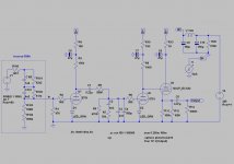
This is my (5751) phono. As you can see, correct filtration and separation is very important for phono stages.
Attachments
Last edited:
- Status
- This old topic is closed. If you want to reopen this topic, contact a moderator using the "Report Post" button.
- Home
- Amplifiers
- Tubes / Valves
- Classi RIAA preamp questions