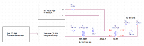
I got to thinking that this $12 30W line-matching transformer might work okay as a single-ended OPT, so I collected a few measurements to share. Test setup is in the first attachment.
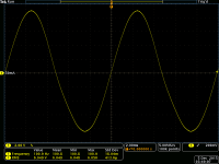
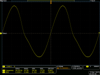
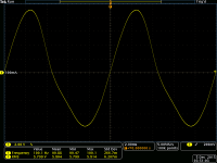
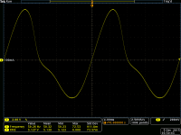
I applied roughly 71VAC (200Vpp) at 1KHz to the 5W primary tap. Primary impedance is nominally 1K at that tap, which includes the whole primary winding. I worked my way down below 100Hz, checking the secondary side waveform for visible distortion with primary DC bias up to 100mA. See attached waveforms, which are annotated. It seems clear that feedback will be necessary to achieve decent LF performance anywhere near 5W, but this could be a challenge worth pursuing.
I applied roughly 71VAC (200Vpp) at 1KHz to the 5W primary tap. Primary impedance is nominally 1K at that tap, which includes the whole primary winding. I worked my way down below 100Hz, checking the secondary side waveform for visible distortion with primary DC bias up to 100mA. See attached waveforms, which are annotated. It seems clear that feedback will be necessary to achieve decent LF performance anywhere near 5W, but this could be a challenge worth pursuing.
Attachments
You would need to take the core apart and gap it for it to work with any decent results.
Well that's unless you use them parafeed. I've found most of these cheap transformers low frequency bandwidth frankly suck to be honest. But I've got no experience with this particular one. Also putting a gap in the core will decrease its low end performance even more.
But in parafeed config you might have a decent contenders. If you don't have a big enough anode choke you could always use a a big resistor for the anode load. Western electric did that for smaller amps. But its wasteful. But for bench work, why not.
Good luck,
Nick
If you would like to see an example of using a large resistor as an output tube plate load in a parafeed amp, take a look at my 6E5P / 6C33C amp.
Audio ratbag: Cat Vomit Special - a 6E5P / 6C33C parafeed amp
I really like this amp, except for the heat which makes it a cold weather amp.
ray
Audio ratbag: Cat Vomit Special - a 6E5P / 6C33C parafeed amp
I really like this amp, except for the heat which makes it a cold weather amp.
ray
Thanks, Ray. The Cat Vomit Special is both hilarious and informative!
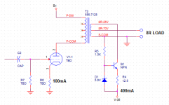
I might try a completely different approach with this little hunk of iron, however: magnetic field cancellation. The secondary has two taps, both for 8R loads, providing hookup options for 70V and 25V distribution systems. The 25V tap has a Pri/Sec turns ratio of about 4, which presumably means that core magnetism nulls with secondary DC bias current 4x primary current. I reckon that a current source to the 25V tap would need +/-25V compliance for 5W output to 8R on the 70V tap. If primary current is, ferinstance, 100mA, then a simple SS current source of 400mA would only have to dissipate 10~20W depending on its power supply voltage and allowed headroom. This crackpot scheme is at least as practical as Cat Vomit, don't ya think?
Cheers,
Mike
I don't think there's any big reason why that wont work fairly well. Maybe if they are cheap enough you could use 4 transformers for more power, although I doubt that will improve the top of the band, and wouldn't work quite so well as equivalent mass in a single core. Typically these little PA transformers don't have great quality nor very thin laminations.
it might get a little hot. Why not put an opposing ccs on the primary? The flux would go through zero either way, which might negate some of the purpose of single ending the active parts.
They sell 30 and 100 watts units also. May be better to start with that if you want bass.
They sell 30 and 100 watts units also. May be better to start with that if you want bass.
Last edited:
Well, this one is rated at 30W nominal. Secondary DCR is 2 ohms, so the added heat in the winding amounts to only 320mW. I like the idea of applying cancellation current to the secondary because it simplifies CCS and PSU design. I've already used this xfmr in a couple of push-pull amplifier projects. It turned in decent results aside from core saturation artifacts at low frequencies. I suspect the low turns-ratio overcomes many of the faults normally attributed to cheap OPTs. If I drive 'em around 5W max with core flux cancellation and a little NFB, I bet I can make a good amp. A very low efficiency amp, for sure, but who's counting?
If you run it like that you'll get saturation distortion and it will sound like cat vomit. Any dc current in a non gapped core will saturate post haste. Plus it will kill your low end even further by making the inductance drop out from saturation.
I hate to say it but what your trying to do isn't likely to work. Why don't you just spend a tiny bit more money and buy 2 edcor xse output transformer. At least then you'll get some positive results with the time you invest in the amp. If you do what's in your schematic all you make is a distortion machine. If your dead set on using these transformers then at least use them with a resistor in parafeed. Otherwise your just spinning your wheel.
I don't want you to discourage yourself by getting bad results from your project here.
Even with dc cancellation I think your still going to run into issue. Why put so much effort into something just to make it work in a sub par way? Then again I can understand if its just something you want to see if you can. You realize that the cancellation current on the secondary will have to be an order of magnitude more current proportional to the winding ratio to work. Plus if there's only one secondary with multiple taps you need to block the dc from going to your speakers.
Nick
Last edited:
.2 volts offset wont ruin most woofers, but you're right it would be there if cancellation were forced secondary side. I guess that'd be .8 volts though, which would start to be a problem. At least it's not just a "5 watt" transformer like I thought. I should have checked the part number before yapping.
True but I wouldn't hook it up to a set of lowthers though. But I do understand the need to just screw around with something just because you can, lol.
I have a pair of very similar transformers that are supposed to work quite well as pp transformers. Though I've never gotten around to do anything with them yet.
I have a pair of very similar transformers that are supposed to work quite well as pp transformers. Though I've never gotten around to do anything with them yet.
You realize that the cancellation current on the secondary will have to be an order of magnitude more current proportional to the winding ratio to work. Plus if there's only one secondary with multiple taps you need to block the dc from going to your speakers.
My working hypothesis: If primary ampere-turns are equal and opposite to secondary ampere-turns, then there's zero net flux in the core. Wrong?
There would be some DC offset at the load due to secondary DCR, of course. I figure 0.35V open-circuit based on secondary DCR measurements. I could eliminate it by grounding the tap instead of the lower end of the winding and rejiggering the CCS. Experience suggests that it's a non-issue, but I'm always grateful for guidance on things like this.
I've been pondering the idea of cancellation without the DC to the speaker problem.
I've used power toroids before such as 115+115:9+9 where the 115 side is wired in series and the 9 side in parallel. It works in parafeed and sounds confused to begin with and then seems to break in after a while.
Could one of the 9 volt windings be used for the current cancellation and the other 9 volt winding connected to the speaker? This would no longer be parafeed of course but similar to BinaryMike's schematic replacing the MCM with a toroid.
ray
Turns ratio would be 25.56:1, which puts secondary bias current just over 2.5A to balance 100mA in the primary. Heating might be significant, depending on winding resistance, but I doubt it. I worry about toroids in this role because they're more sensitive to DC imbalance than EI core transformers.
I wonder if the "confused" sound diminished over time due to gradual core demagnetization.
I'm going to rig an experiment similar to what's in my first post, but including a CCS for flux cancellation this time. I would like to measure core flux density directly, but I'm not aware of any reliable technique that's accessible to amateurs. I do have an old ST distortion analyzer with intermodulation measurement capability, so maybe I'll try that approach.
Okay; so I did the experiment, and it's clear that this method of flux cancellation works as expected. I resurrected an old RCA 40411 power transistor for the CCS, with a 10R emitter resistor, -25VDC supply, and base bias from another output on the same PSU (Agilent E3631A). I kept audio power down to 2.23W in order to stay within CCS compliance. Load resistance was changed to 8R 1%.
Before starting up the DC power supplies, I measured transformer bandwidth at 22Hz ~ 27KHz @-3dB. That includes the rest of my test setup, but the UTC matching xfmr is exceptionally flat. THD at 1KHz was 0.058%
With a 50Hz test signal, 45mA of DC in the primary and zero flux compensation, I measured 10% THD at the load.
At 50Hz and 100mA primary bias I achieved a distortion null of 1.3%, which occurred with secondary bias of 423mA as reported by the PSU. The null felt broad enough to be genuinely useful, but I didn't attempt to quantify that. Cool beans, I say.
I intend to proceed to the breadboard stage, at least. Breadboard work has just been completed on a 20W push-pull amp using this OPT, so I want to build at least one example into a chassis before getting completely distracted. The new project needs a name. How about: CatSkin Amplifier? I'll start a new thread with that title unless something better surfaces before the time comes.
- Status
- This old topic is closed. If you want to reopen this topic, contact a moderator using the "Report Post" button.
- Home
- Amplifiers
- Tubes / Valves
- FYI: MCM 555-7125 Transformer Info