If you think Broskie's take on the WE 'ultrapath' circuit is correct see this:
Ultrapath = Ultra Simple...Except that it's not
If you think Elliano's take is correct leave out the cathode bypass altogether and try a 100uF cap from cathode to B+.
Ultrapath = Ultra Simple...Except that it's not
If you think Elliano's take is correct leave out the cathode bypass altogether and try a 100uF cap from cathode to B+.
Last edited:
Member
Joined 2009
Paid Member
Indeed, Loftin White were a few decades ahead of Broskie in terms of using an injected amount of power supply noise to balance out to zero at the output but he does explain it better and show extensions to the idea, his best one being the Aikido (quite a few of his ideas are recycled but his blog is a great read).
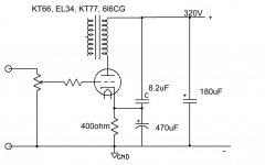
Hello, can you please tell me how to calculate C and if 8,2uF could be a correct value?
Thanks
The impedances of these two capacitors form a voltage divider, so a part of the power supply variations are injected at the cathode, which helps reduce PSU noise and seems to improve bass response also.
The maximum effect is obtained with this formula: C ultrapath = C cathode / µ
Your formula is correct for the case of no psu hum at the power tube grid, i.e. zero hum from the driver stages.
In practice, a little psu hum from the driver can throw this ratio off quite substantially. Another practical issue is that real world caps have quite large tolerances, so it's difficult to match them for optimum cancellation.
In practice, a little psu hum from the driver can throw this ratio off quite substantially. Another practical issue is that real world caps have quite large tolerances, so it's difficult to match them for optimum cancellation.
The impedances of these two capacitors form a voltage divider, so a part of the power supply variations are injected at the cathode, which helps reduce PSU noise and seems to improve bass response also.
The maximum effect is obtained with this formula: C ultrapath = C cathode / µ
Thanks . For µ I can use amplification factor in the following table, I found on
Tubes
correct?
211 2A3 300B 6HV5A
12 4.2 3.9 300
6L6 807 813 8417
8 8 8.5 16.5
EL34 EL84 GM70 KT66
10.5 19.5 6.7 10
6146B 845 KT88 6L6GC
4.5 5.3 8 8
To get zero hum across the secondary (where the speaker connects), both ends of the primary must see equal PS ripple. The upper side of the OPT clearly sees full PS ripple.. hence, the triode plate should also output full PS ripple.
This can be achieved by three ways:
1. Inject a portion of PS ripple at the triode grid
2. Inject a portion of PS ripple at the triode cathode (as your ultrapath circuit intends to do).
3. Combination of 1 and 2.
If you choose 1, the cathode must be ripple free.. If you choose 2, the grid in turn must be ripple free. In your case, it must be assumed that the grid is ripple free so that we can simplify the solution.. There should be no ripple even from the preceding drive stage. If this is fulfilled, we are left with a grounded-grid stage where a portion of the PS ripple is injected at the cathode and amplified at the plate.
Gain of a grounded grid stage is Gain = (mu + 1)Ra / [Ra + rp].
mu and rp should be available at the spec sheet.. Ra is your load impedance (OPT).
To achieve full PS ripple at the plate, the PS ripple injected at the cathode must be 1/Gain in amplitude. This 1/Gain ratio should also then be achieved by your capacitive voltage divider. Let's say the ratio is 1/5 then C ultrapath should be 1/4 of the C bypass.
The formula would be C ultrapath = 1/(gain-1) * C bypass.
Somebody should double check this..
Even if the formula is correct, as goldenbeer mentioned, tolerance of an electrolytic cap is rather high so it might be a futile attempt.
- Status
- This old topic is closed. If you want to reopen this topic, contact a moderator using the "Report Post" button.
- Home
- Amplifiers
- Tubes / Valves
- Ultrapath with cathode bypass cap: which value of C is correct?