The DIY triode tubes that I've been playing with are now at the point where a 1 or 2 watt output triode would seem to be the next obvious windmill to tilt at. The aim of the homebrew vacuum tube project has been focused on 1 tube regenerative radios up until now. The purist approach to getting the audio out these radios is to use high impedance headphones. I got to thinking about the feasibility of making a high impedance dynamic speaker that would have useful SPL's for a desktop or other personal space. The speaker would connect directly to the triode w/o the need for an output transformer.
To get this project going I've made some measurements on a pair of Trimm 2Kohm headphones just to see what I'm up against. One set of magnet coils had 260 Gauss on the pole faces and the other measured 280 Gauss. I have no idea how strong the magnets should be, but I'm sure someone here will know. The coils all measured the same resistance. The gap between the diaphragm and the pole faces was .016" +/- .002". This measurement was done with a rigid bar across the top of the cup. When the steel diaphragm is in place the gap decreases because of its deflection in the magnet field. I still have to measure the degree of this preloading on the diaphragm. Also, one of the pole pieces was somewhat loose and caused the gap on one side of that phone to effectively 'short out'. I'll have to do a dissection when I get the chance.
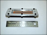
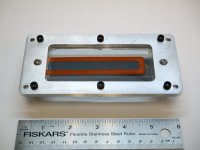
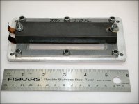
The photos are of a sample prototype of one of the HF drivers that I designed and built way back when. It's now about 25 years old and shows some of it's age. It still works fine, though! I'll use it as a testbed for the high impedance driver. I have some extra parts around here somewhere that will reduce the amount of new machining that will have to be done.
The diaphragm is .6 mil (.0006") polyester film. The voice coil is one turn of 30 microinches (.000030") of copper with a resistance of 2.0 ohms. These were used in line arrays and the sum of the VC resistances could be added for whatever value was desired. Since the VC is only 1 turn and sits above the magnet in the focused fringe gap, its impedance is basically purely resistive in the audio frequency range up to 40 Khz or more. The multi-fiber damping negated the need for electromagnet damping. These drivers make excellent tweeters in a 4 way system using active filters before each power amp. The companion midrange and upper bass drivers are larger versions of similar design.
There must be similar designs to these by now, but I don't think anyone has taken on the challenge of making a free standing high impedance driver (not headphones) yet.
To get this project going I've made some measurements on a pair of Trimm 2Kohm headphones just to see what I'm up against. One set of magnet coils had 260 Gauss on the pole faces and the other measured 280 Gauss. I have no idea how strong the magnets should be, but I'm sure someone here will know. The coils all measured the same resistance. The gap between the diaphragm and the pole faces was .016" +/- .002". This measurement was done with a rigid bar across the top of the cup. When the steel diaphragm is in place the gap decreases because of its deflection in the magnet field. I still have to measure the degree of this preloading on the diaphragm. Also, one of the pole pieces was somewhat loose and caused the gap on one side of that phone to effectively 'short out'. I'll have to do a dissection when I get the chance.
The photos are of a sample prototype of one of the HF drivers that I designed and built way back when. It's now about 25 years old and shows some of it's age. It still works fine, though! I'll use it as a testbed for the high impedance driver. I have some extra parts around here somewhere that will reduce the amount of new machining that will have to be done.
The diaphragm is .6 mil (.0006") polyester film. The voice coil is one turn of 30 microinches (.000030") of copper with a resistance of 2.0 ohms. These were used in line arrays and the sum of the VC resistances could be added for whatever value was desired. Since the VC is only 1 turn and sits above the magnet in the focused fringe gap, its impedance is basically purely resistive in the audio frequency range up to 40 Khz or more. The multi-fiber damping negated the need for electromagnet damping. These drivers make excellent tweeters in a 4 way system using active filters before each power amp. The companion midrange and upper bass drivers are larger versions of similar design.
There must be similar designs to these by now, but I don't think anyone has taken on the challenge of making a free standing high impedance driver (not headphones) yet.
Attachments
One turn? How do you expect that to be high impedance?
The problem with Hi-Z speakers is they require too many turns on the voice coil to be practical.
I suggest you could run DC current thru the single turn and replace the permanent magnet assembly with a high turns coil on a ferrite E core stack along the length. I think there will still be a significant problem with linearity of this design due to the non-uniform magnetic field in a fringing gap. Probably something like 1/r field variation. Possibly some (non-linear) compensation could be provided in the amplifier driving it, but it sure won't be Hi-Fi.
A more likely successful Hi-Z speaker design would just take an existing speaker design, and replace the permanent magnet assembly with a machined (abrasive ground) ferrite core assembly with a high turns field coil on it. DC on the moving armature coil, and audio on the field coil. Won't be very high performance with the low Bsat of ferrite though.
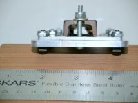
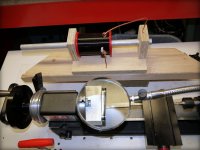
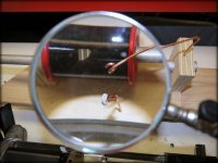
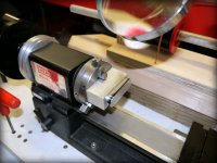
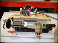
I made some time intermittently this week and started playing with the speaker project again. Using some pieces of stuff from the junk box and having found my stash of high resistance wire, it gave me a head start towards getting something done. The magnetic circuit that I plan to use requires that a racetrack shaped coil be used. Setting up the pantograph to mill the coil former was a snap. Fortunately, there was a Sherline hand threading lathe lying about and in need of some exercise.
As the photos show, it was an easy job to lash together a simple coil winder. The wire is .00275 mil enameled Karma with a resistance of 1.08 ohms/ft. I wound about 25 turns and should have somewhere in the 1 to 1.2 k Ohms. The coil was lacquered while still on the former and it will be interesting to see how well the silicone spray mold release works when the lacquer is dry.
As the photos show, it was an easy job to lash together a simple coil winder. The wire is .00275 mil enameled Karma with a resistance of 1.08 ohms/ft. I wound about 25 turns and should have somewhere in the 1 to 1.2 k Ohms. The coil was lacquered while still on the former and it will be interesting to see how well the silicone spray mold release works when the lacquer is dry.
Attachments
I was able to play with the voice coil today and give it some preliminary tests. I still need to work on getting the coil off of the former more easily, but for a first prototype things went very well. The resistance of the coil was 1070 ohms which was in the predicted range. It had no trouble with a constant 35 mA running through it. my concern was that it might over heat under constant power, but it looks as though the resistance wire isn't going to have a problem with dissipation at this stage.
The next step is to make a new coil former and add some more turns until it looks like a good load for SET amplifier. It will be interesting to see what the coil does in a magnetic circuit. There is a lot more testing to do, but things look very promising for making a high impedance loudspeaker. This is turning out better than I thought it might for so little effort.
The next step is to make a new coil former and add some more turns until it looks like a good load for SET amplifier. It will be interesting to see what the coil does in a magnetic circuit. There is a lot more testing to do, but things look very promising for making a high impedance loudspeaker. This is turning out better than I thought it might for so little effort.
The hi-z speaker made some more progress this week. I was able to attach the ~1K ohm coil onto a piece of thin, 2" wide plastic packing tape and support the tape on a frame similar to the one in the photos posted above. The frame can then be placed over a magnetic circuit as also seen in the above post.
My oscillator for quick tests is a General Radio 1311A. It can directly drive up to 100 volts at 40 ma into a load. This makes it easy to do some simple tests on the voice coils. I was not really expecting how well this arrangement was going to work, so I was pleasantly surprised by the volume it produced at 1 Khz. No windows were broken, but it's working!
Encouraged by these results, I wound another coil with about 75 turns and it's resistance came out to be about 3200 ohms. I'll put it into the magnetic circuit soon and we'll see how it does. It's all very primitive at this point, but these preliminary results are encouraging me to start a new and different coil winding project. I'm looking forward to the multitude of audio testing that is to come!
I'll post some photos when the project looks likes anything that I'd want to show someone.
The coil winding has been so successful to this point that it's time to start looking for the flies in the ointment. So far I haven't been able to get a meaningful inductance measurement from any of my LCR meters, but it's no surprise since the coils' resistances are so high. I could use an online calculator, if there was one for high resistance wire, but I'd rather be forced to dig out the audio test gear. Those instruments needs an occasional warming up, anyhow. I'll do a transfer function impedance curve which should be very telling.
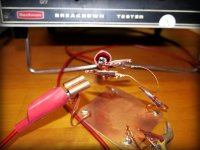
Since I'm lazy by nature and don't want to start wrestling with those tests today, I've decided that a DC breakdown test of the wire's insulation would suffice. Using the fixture that was left over from the construction of the now defunct Pickletron, it was relatively easy to do this test. Fortunately, my shaky hands get very calm after a few beers. So do I. Working with wire that I can hardly see is a real test of its own these days. As Tubalcain says " if it weren't for my OptiVisors, I'd be spending my final days in a rocking chair".
Anyway, the test indicates that the insulation is good for at least 500 volts DC at room temperature. Much more will need to be done to confirm that the dielectric coating (whatever it is) will hold up when it's put to it's task. I can always vacuum pot the coils if necessary.
Attachments
The coil winder has been redesigned and can now wind spiral instead of helical forms. This allows for a very flat coil to to be bonded onto the Mylar film. I wound one yesterday that is twice the length of each of the first 2 helical coils and was able to get about 28K ohms in 40 turns. This geometry makes a single layer coil that is ~.010" thick and ~ .065" wide. These dimensions include the glue that holds the coil together. This allows a nice fit when its in the focused magnetic gap.
Next is to setup some standardized testing arrangement to compare different coils, film substrates, and magnet structures. Since these drivers will be of the dipole radiator type the jig will be mostly to assure reproducible positioning of the panels and microphone and not to try and conform to typical dynamic driver testing. The numbers from these tests will be unique to this setup and are only intended to indicate any progress in construction details.
It's now possible to wind a coil of any reasonable resistance for flat driver voice coils. Next I need to put together an SET rig and see how the drivers sound.
3.1 mil diameter wire, AWG #40, has 1070 Ohms per 1000 feet. So I assume George is using #40 or #41 copper wire, rather than some type of resistive wire.
One certainly would like the DC Ohms to be as low as possible to avoid loss, since it is effectively in series with the AC impedance. The desired AC impedance comes from N turns crossing X amount of magnetic flux at some nominal frequency. So N and X are what need to be optimized. Then the magnetic flux crossing the turns needs to be kept uniform for low distortion as well.
One certainly would like the DC Ohms to be as low as possible to avoid loss, since it is effectively in series with the AC impedance. The desired AC impedance comes from N turns crossing X amount of magnetic flux at some nominal frequency. So N and X are what need to be optimized. Then the magnetic flux crossing the turns needs to be kept uniform for low distortion as well.
I got to do some testing on the new speaker project. The testing was done using the HP analyzer in the FFT mode to do a typical network analysis. This uses a transfer function to evaluate a device for it's impedance characteristics. I chose 2 tweeters of the garden variety, a 3k ohm metal film resistor, and the new voice coil as discribed in a previously posted planar magnetic frame and magnet structure. The frequency range was from 1Hz to 50 Khz.
The results were as suspected they would be, but still were quite amazing. The plots of the 2 tweeters were typical of any dynamic speaker; big hump at resonance and a rising impedance with frequency. The transfer plot of the new coil/speaker and the resistor were identical. Just to test the system for the difference in DC resistance, I connected the 3K ohm resistor in series with the tweeters. The impedance curves of the tweeters were basically the same as before, just lower in level.
Driving the speaker with the GR oscillator with the output set to 160V PP, the audio output was good, but I can't attach useful numbers to it until I get the setup standardized. This is going to work very well from what I can see now.
Now that the basic proof of concept has been established for this new speaker it will be very interesting to continue the testing of prototypes as they emerge. As far as I know this is the only planar magnetic loudspeaker design that incorporates a multi-kohm voice coil with, what appears to be, an almost pure resistance for an output tube to drive. This will allow any SET amp to work into it's optimum load w/o the need for any reactive components in the final signal path. Good-by caps and transformers!
Since I'm still building the newly designed triode driver for this speaker I'll have to simulate an output tube with an arrangement of bench instruments. I'll evaluate most of the tests through the agency of the HP Signal Analyzer. A GR 1311A Audio Oscillator is being used as the proxy output source. The 1311A gives me a 160V PP output and can source 40 ma. My goal is to use a much higher output voltage when the new triode is ready, but it's 'any port in a storm' for now.
Initial tests at spot frequencies in the 1khz -10kHz (the coil is on a tweeter frame) show a distortion level of ~ 0.5%, which is in the area of what the 1311A claims to be good for. I guess that the only surprise so far is that it produces much more acoustical output than I had anticipated for such a crude prototype.
I'll be setting up a test stand for the SPL levels in the days to come and we'll see what the numbers amount to. Dipole radiators aren't the same critters as typical boxed dynamic drivers so this will be an interesting set of tests. The choice of designing this system for 'personal space' use lends itself very well to dipole drivers.
Perhaps I'm misunderstanding something here?
If you replaced the resistance wire in the voice coil with conventional copper wire (of the same gauge) and then connected a conventional resistor in series with that, would you not get exactly the same acoustic output, plus the added benefit of generating the heat in the resistor instead of in the coil?
If you replaced the resistance wire in the voice coil with conventional copper wire (of the same gauge) and then connected a conventional resistor in series with that, would you not get exactly the same acoustic output, plus the added benefit of generating the heat in the resistor instead of in the coil?
Perhaps I'm misunderstanding something here?
If you replaced the resistance wire in the voice coil with conventional copper wire (of the same gauge) and then connected a conventional resistor in series with that, would you not get exactly the same acoustic output, plus the added benefit of generating the heat in the resistor instead of in the coil?
I agree with you. On the face of it, resistance wire would seem to be exactly what one does not want for a speaker coil. One could put a 1 KOhm resistor in series with a normal speaker, and get a similar effect. One may call it a "1 KOhm impedance speaker," but it will be hugely inefficient. Only a miniscule fraction of the electrical power from the amplifier will actually be converted into acoustic power. The fact that the 1 KOhm resistance is distributed through the length of the voice coil wire will not lead to any mitigation of this problem.
Chris
Hopefully, I can answer a couple of questions about the Hi-Z speaker. The output tube requires a resistive load to function properly. This load can be provided in more that one way. I've chosen to provide a purely resistive one and have it do the work to produce the audio output. If I were to use two resistors in series to avoid the need for a transformer, I'd end up with a voltage divider that would split the load between the two. Any loss in the series resistor would steal the power that I'm trying to push through the voice coil. This info is my beer talking and I'm sure that a more grounded view will follow from other more astute followers of this thread.
It doesn't matter whether the 1 KOhm resistor is external, and in series with a low-impedance voice coil made of normal copper wire, or instead is distributed through the voice coil in the form of resistance wire. The two set-ups are essentially equivalent, as far as the calculation of the efficiency of converting electrical power to acoustic power is concerned.
Let's say that the voice coil would have had 8 ohms impedance if it were wound with copper wire, and instead it has resistance of 1000 ohms when wound (same number of turns) with resistance wire. A given acoustic power output requires the same rms current regardless of whether the coil is wound with copper or resistance wire. With the resistance wire, about 99% of the electrical power will be dissipated in ohmic heating in the wire. The mere fact that that ohmic heating is distributed through the length of the resistance wire voice coil rather than an external 1000 ohm resistor doesn't alter the fact that it is electrical power from amplifier that is being wasted as heating. In fact, as was said earlier, it is really worse, because that heating is occurring within the speaker voice coil, rather than in an external 1000 ohm resistor.
Neither option (resistance wire or external 1000 ohm resistor) is going to be very satisfactory, because the acoustic power that can be achieved is going to be equally very small in either case.
Chris
Last edited:
- Status
- This old topic is closed. If you want to reopen this topic, contact a moderator using the "Report Post" button.
- Home
- Amplifiers
- Tubes / Valves
- High impedance speaker for SET OTL amps.