Hi,
When measuring Lundahl LL1677 (4/4+4) as plate load/phase inverter for a E55L stage (despite that datasheet only note SE to SE application), I found out that output of the 2 phases are only even at lower frequencies (<1kHz) but go unevenly at higher frequencies (especially at 10kHz and up).
Anyone here have experienced similar issue and know how to solve it?
Thanks,
Duong
the datasheetHi,
When measuring Lundahl LL1677 (4/4+4) as plate load/phase inverter for a E55L stage (despite that datasheet only note SE to SE application), I found out that output of the 2 phases are only even at lower frequencies (<1kHz) but go unevenly at higher frequencies (especially at 10kHz and up).
Anyone here have experienced similar issue and know how to solve it?
Thanks,
Duong
" http://www.lundahl.se/wp-content/uploads/datasheets/1677.pdf "
limits the current to < 100mA, and recommends 80mA
Whats you current ( and schematic ) ?
the datasheet
" http://www.lundahl.se/wp-content/uploads/datasheets/1677.pdf "
limits the current to < 100mA, and recommends 80mA
Whats you current ( and schematic ) ?
The schema is very simple, just a E55L (8233) in triode mode with this LL6277 as plate load. B+ is 200V, first I ran at 45mA idle current but it showed signs of saturation at below 100Hz so I reduced current to 30mA now. The secondary windings are loaded with two 82k resistor now.
Thanks
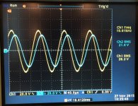
Along with uneven outputs, there's considerable phase shift at higher frequencies as well. Included is waveform of the 2 output from secondary windings (blue channel is inverted for easier comparison).
And I tried terminating the whole secondary winding with a LC network (22k series with 300pF) as suggested in datasheet, it did help a bit with the output level but the phase shift is still there.
Duong
And I tried terminating the whole secondary winding with a LC network (22k series with 300pF) as suggested in datasheet, it did help a bit with the output level but the phase shift is still there.
Duong
Attachments
you haven´t still provided schematic, exact pinout how you wired the transformer..
already measured my irons, symmetrical output. i think you wired something wrong
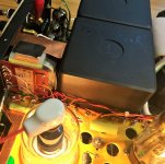
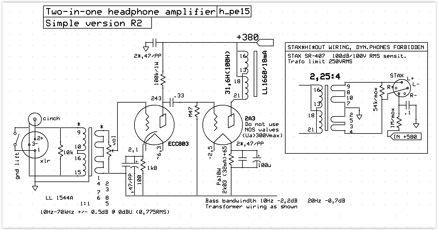
Here's the schema, pretty ordinary I think. The LL1677 is wired follow schema in datasheet, as shown in photo.
And the load on secondary is no longer 82k, I tried replacing them with 10k per leg as you can see in photo, this helped balancing the output up to approx. 25kHz, but I lost a lot of output, distortion probably goes up and the phase shift is still there.
I really hope I wired something wrong, not because this IT is designed solely for SE to SE application

Thanks,
Duong
Attachments

In this situation heavy loading (10K) will probably not effect the distortion much. Not loading transformers enough is often the source of many response issues which represent far more distortion than when adequately loaded. Equal response out to 25khz is probably the best response you can expect and will be more than adequate for HIFI.
Have you checked for ringing on square wave response at various frequencies - this can be a much more serious issue with transformers.
Shoog
Have you checked for ringing on square wave response at various frequencies - this can be a much more serious issue with transformers.
Shoog
Lower drive impedance could make a difference.And the load on secondary is no longer 82k, I tried replacing them with 10k per leg as you can see in photo, this helped balancing the output up to approx. 25kHz, but I lost a lot of output
Try to decouple the 100R cathode resistor.
The wiring of the IT is given in the photo I attached in the previous post: the 2 twisted silver-color-wires go to E55L plate and B+; on the other side, black is common (gnd) and red/orange are the outputs go to next stage.
As I've check for the 100th time myself, the wiring is the same as datasheet, but maybe you can see some difference.
Thanks,
Duong
As I've check for the 100th time myself, the wiring is the same as datasheet, but maybe you can see some difference.
Thanks,
Duong
Attachments
As said before, please give details of exactly how you wired up the pins. Its quite complex on the datasheet so checking that this is right is worthwhile.
Shoog
that is what i been thinking, since ludahls are sectioned, inner-outer windings have slightly different parameters.
this is more important, when windings are wired in paralel
remeasured it again, on sine even at 40khz looks symmetric, +-1-2v diff between two outputs. 70rms on each half
however on squares, above 10khz it starts looking funny, ringing and partial mirrored picture, bigger difference.
bass, mid absolutely ok.
(stax plugged in, iron is floating....)
i may rewire secondaries later to have more symmetry
primaries are DCR equal, best case scenario, thats why used trafos backwards
Last edited:
remeasured it again, on sine even at 40khz looks symmetric, +-1-2v diff between two outputs. 70rms on each half
however on squares, above 10khz it starts looking funny, ringing and partial mirrored picture, bigger difference.
bass, mid absolutely ok.
(stax plugged in, iron is floating....)
i may rewire secondaries later to have more symmetry
primaries are DCR equal, best case scenario, thats why used trafos backwards
If I understand correctly, you're using LL1660, and its datasheet does mention SE to PP application.
Furthermore, this is what I got from Lundahl about my case
Looks like I have to change my choice of IT.Yes, I am afraid it is not surprising that you find considerable amplitude difference and phase shift when the LL1677 is used as described. Transformers designed for phase splitting in SE-PP applications should have internal Faraday shields to reduce the difference in output phase and amplitude. I am afraid the LL1677 does not have any such Faraday shield.
Duong
 will go amorph 1660S
- Status
- This old topic is closed. If you want to reopen this topic, contact a moderator using the "Report Post" button.
- Home
- Amplifiers
- Tubes / Valves
- Uneven output from LL1677