Hi, folks. I have ben lurking for a while and have decided to take the plunge into Valve amplifiers. I thought this kit seems good value and therefore worth a risk as a first project. I fully understand that as a cheap kit it is not going to be earth shattering but I thought that it would give me an opportunity to try things out.
Obviously it will come with cheap components so my first question is are there any particular components that would make a big difference if I bought something better? I was initially thinking about the coupling capacitors. Are there other passive components worth changing?
What is the opinion on the feedback element? Would an alternative value make significant difference? should I try some alternative values here if so what should I try?
Any suggestions gratefully received
Thanks AVO111
The OPT's (Output Transformers) make the biggest improvement
sonically on a tube amp so save up and buy the best you can afford.
You might look at what EE George Anderson has on his tubelab.com
site as he sells very popular & affordable PCB's and has lot's of info
on his site and forum on this site.
Tubelab | Dedicated to advancing the state of the art in affordable high end audio.
Without seeing the specifics of the kit it is hard to advise, do you have a link?
I use a similar circuit chinese amp.
I ended up having to replace the power switch which was flimsy and stopped turning off. The speaker terminals did not match the chassis holes and could have shorted.
the volume pot is small and flimsy.
The transformer as supplied ran hot and I replaced it with one from Douk
Jefff this is what I bought
6N9P+EL34B Class A Single-ended 13w+13w Tube AMP Amplifier Hifi Valve DIY KIT | eBay
I am open to ideas and am looking around on the web to see if there is a better way to use this kit than build as they describe") I am happy to play around as long as I learn something from the exercise
I am happy to play around as long as I learn something from the exercise
6N9P+EL34B Class A Single-ended 13w+13w Tube AMP Amplifier Hifi Valve DIY KIT | eBay
I am open to ideas and am looking around on the web to see if there is a better way to use this kit than build as they describe
I am happy to play around as long as I learn something from the exerciseAs already mentioned here, the output transformer of cheap kits is usually the component that mostly limits the performance.
Those OPTs look a little bit undersized, but I suggest you first build the amp as it is and make modifications later when you know what the real performance is.
Those OPTs look a little bit undersized, but I suggest you first build the amp as it is and make modifications later when you know what the real performance is.
Folks,
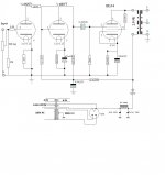
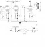
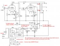
I have just found another schematic for what appears to be the same kit. The principal difference is in the input stage where the 6N9P is wired as a two stage rather than the first schematic that seems to wire both triodes in parallel. Can you advise what the effective difference will be with these two different approaches to the input stage? I note this second version has a bias connection to the 6N9P heater, is this something that should be included in the first schematic as the difference between anode and heater voltage will be the same in both designs or am I missing something?

I have just found another schematic for what appears to be the same kit. The principal difference is in the input stage where the 6N9P is wired as a two stage rather than the first schematic that seems to wire both triodes in parallel. Can you advise what the effective difference will be with these two different approaches to the input stage? I note this second version has a bias connection to the 6N9P heater, is this something that should be included in the first schematic as the difference between anode and heater voltage will be the same in both designs or am I missing something?
Those two 6N9P are connected as a SRPP circuit. It's main advantage is lower output impedance than what typical common cathode amplifier has.
In this case there is no obvious benefit achieved, because the output stage is pentode connected EL34, which can be well driven with a single 6N9P.
In this case there is no obvious benefit achieved, because the output stage is pentode connected EL34, which can be well driven with a single 6N9P.
I assembled this circuit before exactly the one you posted and my comments is not as good as this one which I assembled recently.Hi, folks. I have ben lurking for a while and have decided to take the plunge into Valve amplifiers. I thought this kit seems good value and therefore worth a risk as a first project. I fully understand that as a cheap kit it is not going to be earth shattering but I thought that it would give me an opportunity to try things out.
Obviously it will come with cheap components so my first question is are there any particular components that would make a big difference if I bought something better? I was initially thinking about the coupling capacitors. Are there other passive components worth changing?
What is the opinion on the feedback element? Would an alternative value make significant difference? should I try some alternative values here if so what should I try?
Any suggestions gratefully received
Thanks AVO111
View attachment 512065
Attachments
Opps make a mistake. Edit my circuit.I think you made a mistake in your drawing Pin 1 and 2 may not have a connection.
Attachments
What you have in the 2nd schematic is a SRPP input stage with a lowish output impedance. There's no bias connection to the tube, just a poorly designed psu which fires anything in the box. There should be a separated ps for the heaters.
The sonic difference between a SRPP and a pse stage is huge. Although the first one is quite popular, personally I don't like it.
The sonic difference between a SRPP and a pse stage is huge. Although the first one is quite popular, personally I don't like it.
That is your own opinion. I'm more concerned about the outcome.What you have in the 2nd schematic is a SRPP input stage with a lowish output impedance. There's no bias connection to the tube, just a poorly designed psu which fires anything in the box. There should be a separated ps for the heaters.
The sonic difference between a SRPP and a pse stage is huge. Although the first one is quite popular, personally I don't like it.
Ok celestar what is your concern about the outcome? I would like to build this so the smoke stays in the wires and the sound is as good as possible ! We are already up to 3 alternate schematics using pretty much the same components in the kit! As I said I am on a mission to learn here and quite interested in building in options so I can hear differences. Do not worry about my safety I am quite experienced in dealing with potentially lethal voltages ranging from live 3 phase to 30kv neon transformers driving a Jacobs ladder! Seriously options for learning are good for me here!
AVO111
Caber
AVO111
Caber
I'm happy with the sound outcome with this circuit. Previously was using 6SL7 but change to this circuit using 6SN7, it was better.Ok celestar what is your concern about the outcome? I would like to build this so the smoke stays in the wires and the sound is as good as possible ! We are already up to 3 alternate schematics using pretty much the same components in the kit! As I said I am on a mission to learn here and quite interested in building in options so I can hear differences. Do not worry about my safety I am quite experienced in dealing with potentially lethal voltages ranging from live 3 phase to 30kv neon transformers driving a Jacobs ladder! Seriously options for learning are good for me here!
AVO111
Caber
It's arrived
Folks,
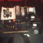
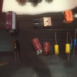
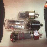
Well the kit turned up today having had a nice tour of the far East thanks to mis routing by Fed-Ex! Overall it seems OK, many of the comments I have seen about build quality seem fixed and it even comes with a well ventilated bottom plate. Here are some pictures of the components attached ( i hope
First question is the capacitors. The two yellow ones are the coupling between stages. They are labeled BENNIL will they be OK or what would you suggest I should get to replace these? The carbon resistors seem all to be brown where I am expecting the tolerance band. does this likely mean they are 20 % if so should I get tighter tolerance for any specific resistors in the schematic?
I am planning to build the one I first posted however I want to add additional line inputs so I was proposing just to add a rotary switch and some more RCA connectors.
i am also wondering about adding an alternate value resistor in the feedback loop just to see the audible difference. Any suggestions what I should have as alternate for the 2K in the schematic?
Thanks AVO 111
Folks,
Well the kit turned up today having had a nice tour of the far East thanks to mis routing by Fed-Ex! Overall it seems OK, many of the comments I have seen about build quality seem fixed and it even comes with a well ventilated bottom plate. Here are some pictures of the components attached ( i hope
First question is the capacitors. The two yellow ones are the coupling between stages. They are labeled BENNIL will they be OK or what would you suggest I should get to replace these? The carbon resistors seem all to be brown where I am expecting the tolerance band. does this likely mean they are 20 % if so should I get tighter tolerance for any specific resistors in the schematic?
I am planning to build the one I first posted however I want to add additional line inputs so I was proposing just to add a rotary switch and some more RCA connectors.
i am also wondering about adding an alternate value resistor in the feedback loop just to see the audible difference. Any suggestions what I should have as alternate for the 2K in the schematic?
Thanks AVO 111
Attachments
- Status
- This old topic is closed. If you want to reopen this topic, contact a moderator using the "Report Post" button.
- Home
- Amplifiers
- Tubes / Valves
- Douk EL34 Amp kit