What would changing C1 to .00391 do?
That would affect the RIAA correction, probably reducing the higher frequencies by several dB for one thing.
Last edited:
I realize that, but how would the sonics be changed?
Similar to turning the treble tone control down part way.
Would changing R1 to 20K and C1 to .00391 restore the original top end performance?
If you want to define C1 as 3.91 nF, the RIAA circuit can be redesigned, but all of the other parts in the RIAA will change their values.
Don't forget the source impedance of the first tube stage, which affects the value of R6.
Similar to turning the treble tone control down part way.
Yes, C1 affects mainly at 75uS.
and remember... C4 = 3 x C1.
Cheers
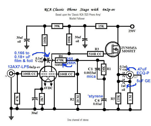
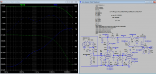
I just finished the simulation of RCA photo with MOSFET buffer stage you attached and found few issues:
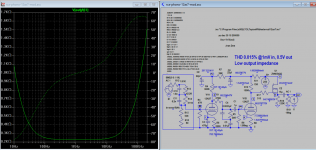
1) With zero cathode resistance on the 2nd triode, distortion is as high as 5%, min value I found is 5 ohms.
2) For output coupling cap of 0.1uF the output impedance below 100Hz is very high, 15K compared with less 1K above 1Khz. So I increase the value to 15uF and the output impedance is as low as 1K down to 10Hz.
3) 20 Meg bias resistor to compensate for bottom end? There is stability concern for current more 1mA. So I mod that too.
Here are some snapshots for sharing.
Attachments
Koonw the second stage uses grid leak bias, and most tube models I am aware of don't model grid current behavior correctly - why not build the thing as designed; I think you will find it performs quite a bit differently from your predictions.
That 0.1uF cap could be increased, but 15uF is way beyond reasonable, you don't really want to be amplifying the arm/cartridge compliance resonance any more than you have to. I'd say 0.47uF is at or beyond the point of diminishing returns.
That 0.1uF cap could be increased, but 15uF is way beyond reasonable, you don't really want to be amplifying the arm/cartridge compliance resonance any more than you have to. I'd say 0.47uF is at or beyond the point of diminishing returns.
Lugnut, despite all of the hype around mica caps in RIAA EQ circuits, even the much vaunted Russian silver micas I just have not found them to be subjectively acceptable although apparently many do. I tried to love them, but alas they got replaced with small films. (Teflon or polystyrene)
despite all of the hype around mica caps in RIAA EQ circuits, I just have not found them to be subjectively acceptable.
they got replaced with small films. (Teflon or polystyrene)
Yes, and the Rel-Cap RTE types are very good, as were the old Siemens polypropylene films.
BTW, I much preferred those over Siemens own polystyrenes at the time, and it was not even close.
They were so good and cheap that I bought lots, and sorted and matched them in pairs to 0.1% for RIAA circuits.
Last edited:
Personally, I would listent advices from Eli and Kevin about this preamp.
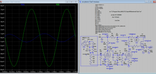
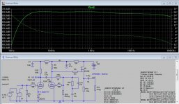
I simulate this RIAA with old Phillips BSS89 fet.
Depending on the 12AX7 model, maximum THD is 3.3% @ Vout = 2.4 V (Nakabayashi model) and only 0.02% !!! (Audiomatica model). Other models are somewhere in between.
I simulate this RIAA with old Phillips BSS89 fet.
Depending on the 12AX7 model, maximum THD is 3.3% @ Vout = 2.4 V (Nakabayashi model) and only 0.02% !!! (Audiomatica model). Other models are somewhere in between.
Attachments
Lugnut, despite all of the hype around mica caps in RIAA EQ circuits, even the much vaunted Russian silver micas I just have not found them to be subjectively acceptable although apparently many do. I tried to love them, but alas they got replaced with small films. (Teflon or polystyrene)
Agreed. Polystyrene for me.
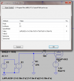
Didn't know this method. Works really fine, thanks Kevin!Here's a purely mathematical way to implement an inverse RIAA in LTSpice using the LaPlace transform.

Here's a purely mathematical way to implement an inverse RIAA in LTSpice using the LaPlace transform. (Convert behaviors specified in terms of time domain i.e poles at 3180us and 75us, and a zero at 318uS into frequency domain)
An externally hosted image should be here but it was not working when we last tested it.
Man I need to brush up on my Laplace HAHAHA

John Broskie made a program called TCJ RIAA that models various passive RIAA EQ networks. It's not totally flexible, but playing with it can give you an idea of how all the various parts values in an all-in-one-go RIAA EQ network are very interactive. Change one value and you have to change the others to compensate. Change tube type and the different rp of that tube causes the EQ to completely change, so you have to re-design the whole thing. The program's fun, and I think it's pretty accurate as long as you enter all the parameters correctly (such as adding a series resistance Rs that matches the rp of the input stage).
Index of /files/Programs
--
Index of /files/Programs
--
- Status
- This old topic is closed. If you want to reopen this topic, contact a moderator using the "Report Post" button.
- Home
- Amplifiers
- Tubes / Valves
- Radiotron/Eli Duttman phono change C1 to .00391?