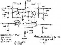
Tried my hand at designing a new driver for an old ST70 chassis. The driver is a differential shunt cascode using a triode connected 6P15P pentode (lower) with a MJE5842 (upper). I have kept it as simple as possible with only one current source on the 6P15P cathodes. Perhaps I have over iced the anode current but wanted maximum transconductance from the 6P15P. The gain is theoretically 160 and there should be plenty of swing. Inputs are balanced and the output stage will be a push pull GU50 pentode pair operating with 25% CFB (Lundahl 1620 CFB). No global feedback. Alternative output stage is a Schade feedback arrangement with the insertion point at the 10k/1uF junction. Any opinions or suggestions would be welcome. Sorry no fancy cad drawing, by hand much much quicker.
Attachments


Nice to see a shunt-cascode development - Good work!
My comments:
1. The high gain that shunt-cascode offers makes the PNP oscillate (2-50MHz) unless Ferrite beads are added to the base, emitter and output connexions. wiring from base/emitter to the beads must be very short.
2. try to keep the transistor power dissipation low - then you can use a low capacitance type MPSA92 (300V) or KSP94 or PZTA94 (400V). These types keep the HF distortion low.
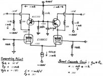
3. Try to get the anode voltage of the driver equal to the maximum positive swing you need. This helps keep the PNP power low.So I like Ketje's E188CC with its 90V... this will give excellent performance.
4. Using PNP in darlington connexion (2x MPSA92) renders the base-current error very small, i.e. lowers distortion.
5. Base voltage should be a stiff as possible - I use a PNP follower for the divider network, pulled high with 1mA CCS.
A shunt regulator may not be overdoing it, when highest performance is desired.
6. Resistor for a CCS is worth a try, but CCS may give better performance. Try and see!
My comments:
1. The high gain that shunt-cascode offers makes the PNP oscillate (2-50MHz) unless Ferrite beads are added to the base, emitter and output connexions. wiring from base/emitter to the beads must be very short.
2. try to keep the transistor power dissipation low - then you can use a low capacitance type MPSA92 (300V) or KSP94 or PZTA94 (400V). These types keep the HF distortion low.
3. Try to get the anode voltage of the driver equal to the maximum positive swing you need. This helps keep the PNP power low.So I like Ketje's E188CC with its 90V... this will give excellent performance.
4. Using PNP in darlington connexion (2x MPSA92) renders the base-current error very small, i.e. lowers distortion.
5. Base voltage should be a stiff as possible - I use a PNP follower for the divider network, pulled high with 1mA CCS.
A shunt regulator may not be overdoing it, when highest performance is desired.
6. Resistor for a CCS is worth a try, but CCS may give better performance. Try and see!
Last edited:
Thanks for the Suggestions
Ketje and Rod
Thanks for your input, much appreciated. I was looking at Allen Wrights differential cascode design last night and he operates the bottom tube at a fairly low voltage and high current (75V and 12.5mA) similar to Ketje's design. Although Allen's is a series cascode and mine is shunt, in principle the two active devices do the same function.
Rod will try your suggested transistors and tighten the base voltage but will stick with the loading resistors rather than CCSs for now. Little steps.
What's the point of using tubes at all if you're putting transistors in there anyway? And in the wrong places, besides; back before the days of good performance high voltage transistors, a fast but low voltage transistor would be used to drive a larger tube from below (typically 6DJ8, 6DK6 or 12BY7, in many Tektronix examples from the 50s and early 60s).
But this is doubly, or even triply useless, because your application needs low distortion, modest to low bandwidth, and does not suffer from matters of cost or availability!
Tim
But this is doubly, or even triply useless, because your application needs low distortion, modest to low bandwidth, and does not suffer from matters of cost or availability!
Tim
Seems like leaving the 6P15P as a pentode does almost the same thing.
If one is going to put P type SS up top, one could put current mirrors or even current mirrors with current gain up there.
Shunt Cascode gives gain of 200-300 easily, at lower distortion than a pentode. This makes for a better single-stage 300B or GM70 driver in short.
What's the point of using tubes at all if you're putting transistors in there anyway? And in the wrong places, besides; back before the days of good performance high voltage transistors, a fast but low voltage transistor would be used to drive a larger tube from below (typically 6DJ8, 6DK6 or 12BY7, in many Tektronix examples from the 50s and early 60s).
But this is doubly, or even triply useless, because your application needs low distortion, modest to low bandwidth, and does not suffer from matters of cost or availability!
Tim
Tim, please analyse more carefully.
The transistor is acting as a constant-voltage load for the triode - steering the current and allowing the stage to function as a simple transconductance amplifier with a ground- or negative-referenced output.
IOW, the triode runs a vertical load-line. Unconventional, but many triodes have very low distortion in this mode - especially those like the tuner triodes, which were designed for grounded-grid or cascode - constant-voltage condition. Other good candidates - including triode-connected pentodes - can be found by measurement.
This technique allows the building of a very high quality single-stage driver for large output valves - using cheap and unwanted (but first-rate quality) TV triodes like the PC86, Russian 6С3П [6S3P] and many others.
Using a transistor in the downstairs position would give much higher open-loop distortion.
And simple high gain, more NFB possibleUsing a transistor in the downstairs position would give much higher open-loop distortion.

Mona
Attachments
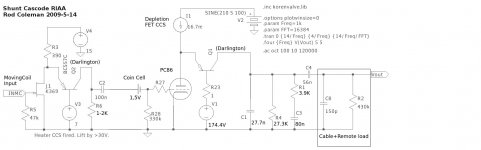
Nice, but that one isn't in the right placeWell, if you want an MC + RIAA amplifier, shunt cascode gives even better results!
Mona
Attachments
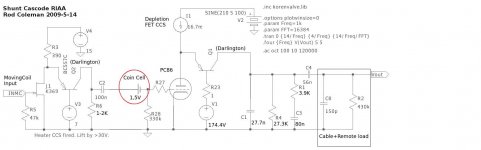

Yes, I am modding the drawing too fast!
Please remove C2 and R28 in the drawing.
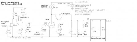
Oh ? I was more thinking something like this
Mona
Attachments
IOW, the triode runs a vertical load-line. Unconventional, but many triodes have very low distortion in this mode - especially those like the tuner triodes, which were designed for grounded-grid or cascode - constant-voltage condition. Other good candidates - including triode-connected pentodes - can be found by measurement.
And this invalidates my analysis, how? I think you're just acknowledging my point...
All triodes at constant Va exhibit Ia ~ Vg^(3/2) power law behavior. There are no "low distortion" triodes in this operation. I'm not sure where you heard that, but they're quite incorrect, and testing this circuit near clipping will illustrate this clearly.
Triodes made for RF applications typically have appalling transfer curves, because they only need to handle enough current to get the transconductance required; distortion wasn't a problem (they're amplifying millivolts), and indeed many were intentionally made worse (semi- or fully remote-cutoff characteristics, for use with AGC).
Consider the poor rep such tubes as 12AT7 have in the hifi crowd. They're pretty neat for RF, but not much value for large signals.
6DJ8 being an odd exception, but it looks cool, and has unusually great specs (even at audio). The extra gain means you can bleed more off with NFB to get an even better result.
Using a transistor in the downstairs position would give much higher open-loop distortion.
And several orders of magnitude more gain; when emitter degenerated to the same transconductance, the distortion will be, in turn, one or two orders of magnitude lower. (Whereas you might need a triode cascode, or pentode, to realize a certain amount of gain required for an audio amplifier, a single transistor can do it with headroom to spare.)
In the grand scheme of things, the exponential transfer curve of the BJT is of much greater value (e.g., high gain, easy to implement multipliers) than hindrance (distortion, uncertainty in Ic vs. Vbe), and anywhere you try to compare them on equal footing, the orders of magnitude in gain just trounces anything, no matter how you cut it.
And sure, you can make hand-wavings about "desirable distortion", but that too has to be balanced carefully (more than so-and-so percent is again undesirable), and isn't beyond reproducibility anyway (a few transistors could be configured in such a way as to behave more-or-less like a triode).
Tim
And this invalidates my analysis, how? I think you're just acknowledging my point...
All triodes at constant Va exhibit Ia ~ Vg^(3/2) power law behavior. There are no "low distortion" triodes in this operation. I'm not sure where you heard that, but they're quite incorrect, and testing this circuit near clipping will illustrate this clearly.
Triodes made for RF applications typically have appalling transfer curves, because they only need to handle enough current to get the transconductance required; distortion wasn't a problem (they're amplifying millivolts), and indeed many were intentionally made worse (semi- or fully remote-cutoff characteristics, for use with AGC).
Consider the poor rep such tubes as 12AT7 have in the hifi crowd. They're pretty neat for RF, but not much value for large signals.
6DJ8 being an odd exception, but it looks cool, and has unusually great specs (even at audio). The extra gain means you can bleed more off with NFB to get an even better result.
Tim
Tim,
There is no need for you to make generalisations of this kind.
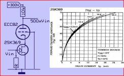
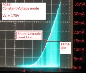
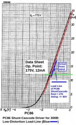
If you had taken the hint I offered, and looked at the actual data of the PC86, you would see that is exceedingly linear in constant-voltage mode. And should that not suffice, see also the actual curve-trace of a sample at Va=175V.
to make it easy this time, I have attached the curves, which show the whole and actual picture.
This has already been thoroughly debated before, to the grudging acceptance of other gainsayers - please search the forum for more details.
Please put down that text book, and measure!
Attachments
And several orders of magnitude more gain; when emitter degenerated to the same transconductance, the distortion will be, in turn, one or two orders of magnitude lower. (Whereas you might need a triode cascode, or pentode, to realize a certain amount of gain required for an audio amplifier, a single transistor can do it with headroom to spare.)
In the grand scheme of things, the exponential transfer curve of the BJT is of much greater value (e.g., high gain, easy to implement multipliers) than hindrance (distortion, uncertainty in Ic vs. Vbe), and anywhere you try to compare them on equal footing, the orders of magnitude in gain just trounces anything, no matter how you cut it.
And sure, you can make hand-wavings about "desirable distortion", but that too has to be balanced carefully (more than so-and-so percent is again undesirable), and isn't beyond reproducibility anyway (a few transistors could be configured in such a way as to behave more-or-less like a triode).
Tim
Please do not put words into my mouth about desirable distortion - I have said nothing of the kind.
If you are claiming marvellous performance from your solid-state design, please build and measure, and we can see.
PC86, sounds familiar.
Page 6 of the datasheet shows S or gm is not staying constant. They probably drew the current curve with a ruler back then. Straight line requires constant S or gm. You cannot tell from the I curve when it gets near vertical.
http://frank.pocnet.net/sheets/010/p/PC86.pdf
Page 6 of the datasheet shows S or gm is not staying constant. They probably drew the current curve with a ruler back then. Straight line requires constant S or gm. You cannot tell from the I curve when it gets near vertical.
http://frank.pocnet.net/sheets/010/p/PC86.pdf
- Status
- This old topic is closed. If you want to reopen this topic, contact a moderator using the "Report Post" button.
- Home
- Amplifiers
- Tubes / Valves
- Differential Shunt Cascode Driver