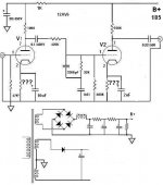
I have decided to built the Phone pre-amp from the RCA tube manual.
But I want to make some changes, mainly the tubes. I have 12AV6's on hand
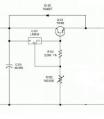
so I will use them. I will build a regulated power supply using the LR8N3-G
with a pass transistor. The max voltage my power supply can provide is 200vdc.
I will regulate this down to 185vdc.
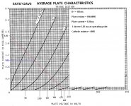
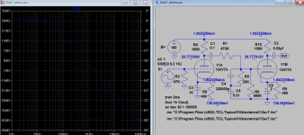
I made the calculation seen on the load line chart.
This is a learning exercise for me so Please don't suggest other circuits.
Are my lines and cathode resistor value correct?
Thanks...
But I want to make some changes, mainly the tubes. I have 12AV6's on hand
so I will use them. I will build a regulated power supply using the LR8N3-G
with a pass transistor. The max voltage my power supply can provide is 200vdc.
I will regulate this down to 185vdc.
I made the calculation seen on the load line chart.
This is a learning exercise for me so Please don't suggest other circuits.
Are my lines and cathode resistor value correct?
Thanks...
Attachments
Are my lines and cathode resistor value correct?
Looks fine to me. Real world results will be a little different because the tubes will pull a little grid current so near zero bias. But your method is correct!
All good fortune,
Chris
You can check it here http://www.diyaudio.com/forums/tubes-valves/260908-triode-pentode-loadline-calculator.html
Mona
Mona
Hi Bruce
Sure, use ~500 ohm to bias your cathode. If my quick calculation is correct, you should at the very least use 40uF to bypass that cathode resistor though. I would suggest a 100uF cap. Please do the calculations yourself though to be certain - I always need to triple check my own values.... Morgan Jones is an excellent reference for this!
F = 1/(2 * pi * C * R) or more conveniently C = 1/(2*pi*F*R) where F is your corner frequency in Hz and C will be in Farads - you will likely want to convert it to uF
R is equal to Rk in parallel with (Ra + rp)/(mu + 1) I get something like R = 380 Ohm in your proposed circuit...
Also, I would put the follower resistor before the coupling capacitor. I didn't check your RIAA values. According to the RCA specs sheet, the plate resistance is 80k Ohm - this needs to be included in your passive RIAA correction as well.
Not sure how you wish to bias the second triode. Your output will not likely have a fairly high impedance, so I hope the connection to the next stage is short. Long cables won't work well here...
Kind regards
Ian
Last edited:
I've been listening to a version of this circuit today. I hope you don't mind me making a few suggestions...
First, I'll second marcelop's suggestion to run the tubes at a bit lower plate current. This should allow you to get the grid-cathode voltage high enough to keep the 12AV6s from drawing grid current. I think you might want to shoot for marcelop's suggestion of a -1V grid bias rather than something like -0.5V. I remember reading that moving magnet cartridges do not work well into an input stage with grid current.
From your loadline, it looks like you could get Vp = 115V, Vk = 1V, Ip = 0.7mA. I think a cathode resistor of 1.5k would get you pretty close, as 1V/1500R = 0.67mA.
Interestingly, Fender guitar amps used those same plate and cathode load resistor values, 100k in the plate, 1.5k in the cathode. With a 47uF cathode bypass cap, I get F = approx 3.5Hz.
Regarding soulmerchant's point that the output impedance will be really high, I have a question: Are you making a standalone phono preamp, or is this going straight to a line stage with gain, inside a 'control preamp'? If it's a standalone phono preamp, I'd look at adding a cathode follower or an FET follower on the output. The high input impedance of the follower will make life much easier for the second stage, and its much lower output impedance will have a better chance of driving cable capacitance and any potentiometer losses. If the phono preamp without a follower tries to drive a a couple feet of cable and a 100k pot, I'd expect there would be a loss of gain and an increase in distortion.
In the version I made, I used the stock RCA circuit using 12AX7s but with a +300V plate supply, and DC-coupled the plate of the second stage to a 12AV7 cathode follower (mostly because I already had a sleeve of those tubes and it was easy to get it working in this particular circuit). I really like the result.
To help you figure out more accurate R and C values for your particular operating conditions, you might want to take a look at John Broskie's TCJ RIAA app. However, I modeled the original RCA EQ values in LTspice and it came out pretty accurate. There's a lift of about 0.5dB in the mid-bass and 0.2dB around 10kHz, but that sounds 'good.'
Have fun with this. You might find that you really like it.
RonG
--
Last edited:
I have decided to built the Phone pre-amp from the RCA tube manual.
But I want to make some changes, mainly the tubes. I have 12AV6's on hand
so I will use them. I will build a regulated power supply using the LR8N3-G
with a pass transistor. The max voltage my power supply can provide is 200vdc.
I will regulate this down to 185vdc.
I made the calculation seen on the load line chart.
This is a learning exercise for me so Please don't suggest other circuits.
Are my lines and cathode resistor value correct?
Thanks...
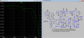
I plug in 490 ohm, distortion wise OK, but it's does not look like RIAA curve of +-20db over 10hz-20Khz. Are all other components value correct? The response should go down slope near 10hz, not 1Khz.
Attachments
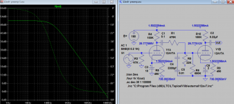
I tried 12ax7 which has nearly same mu and rp is the same slope. So if I increase C4 by 100 time (1000/10=100) from 3300p to 330000p, this is getting closer to RIAA curve.Hi Koonw,
I think your model has 12AV7 tubes in it. The circuit in question will be using 12AV6, which is pretty much identical to a 12AX7, but in a 7-pin mini bottle. That might be why the EQ in your model comes out so far off.
--
Attachments
Your output will not likely have a fairly high impedance, so I hope the connection to the next stage is short. Long cables won't work well here...
What I meant to write is output will have a fairly high impedance... sorry if this was unclear in my post. The suggested solutions from rongon are useful.
Last edited:
Here is an example of this circuit with 12ax7 you might find useful to compare against:
It is in an integrated amplifier. The suggestions of rongon to elevate the plate supply (for your implementation) are very good to consider as well.
An externally hosted image should be here but it was not working when we last tested it.
It is in an integrated amplifier. The suggestions of rongon to elevate the plate supply (for your implementation) are very good to consider as well.
Last edited:
I plug in 490 ohm, distortion wise OK, but it's does not look like RIAA curve of +-20db over 10hz-20Khz. Are all other components value correct? The response should go down slope near 10hz, not 1Khz.
RIAA curve and playback correction Linked from wikipedia

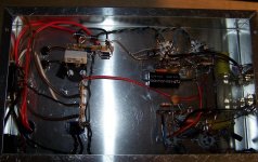
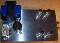
A few pictures, It's a work in progress. I'm making changes as I go along with
your help. Parts on order to build the B+ regulator. I tried heating the tubes with
AC, unregulated DC, and car battery, results about the same. The reg. B+ I hope will cure the noise. Once I get all the bugs worked out, I will strip it clean
and start from the ground up with all the mods.
It will be a stand-alone driving a 3 foot cable going into my computer. I don't
see a problem here. As it is now, it sound very good except for the background
noise.
Thanks again
Attachments
Hello All,
Very valuable information. Thanks you for helping.
Bruce
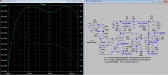
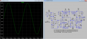
I'm sorry I made a mistake in C5 should be 0.01uf not 0.01f. So here is the full sim of original RCA phono amp. And sim model, if you spot any other error let me know.
Attachments
It will be a stand-alone driving a 3 foot cable going into my computer. I don't
see a problem here. As it is now, it sound very good except for the background
noise.
Thanks again
I'm sorry, I think there likely is a problem. The input impedance of the pc's line in is probably low, like 10k. That will severely load down a 6AV6/12AX7. Much reduced gain may be causing noise. Some kind of buffer or matching transformer is desirable here.
--
I'm sorry I made a mistake in C5 should be 0.01uf not 0.01f. So here is the full sim of original RCA phono amp. And sim model, if you spot any other error let me know.
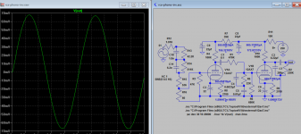
Koonw, can you substitute a 10k resistor for R2, and show us the results? That will simulate how this circuit will react to driving a low impedance input, as on a PC sound card. Keep an eye out for what happens to the gain.
--
Koonw, can you substitute a 10k resistor for R2, and show us the results? That will simulate how this circuit will react to driving a low impedance input, as on a PC sound card. Keep an eye out for what happens to the gain.
--
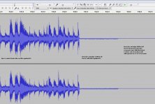
Here are the results. Overall gain drops by about 13db more below 15hz, 1Khz gain drop from 70mV to 15mV but distortion remains same as ~0.05%
Attachments
- Status
- This old topic is closed. If you want to reopen this topic, contact a moderator using the "Report Post" button.
- Home
- Amplifiers
- Tubes / Valves
- Someone, please check my plot.