Just omit C4 from the circuit will do. The output stage is supposed to have unity gain so it should not be mod again. When R11 & R12 is reduced to 50K the overall gain reduced by half.
Hi
")
If feedback resistors are 33k, what is the gain and THD?
I have a bunch of old 6n1P (not sure how gassy they are though) and would like to see what they can do. Thankfully I also have the possibility of 250V or B+ and a nice 12.6V transformer to power series heaters.
I assume this schematic would require me to float the heater above ground? About 60V or so?
I need about 10dB gain (3V/V) but 12-14 would be fine too. I have some amps with low gain and sources with low outputs.
Last edited:
Hi
If feedback resistors are 33k, what is the gain and THD?
I have a bunch of old 6n1P (not sure how gassy they are though) and would like to see what they can do. Thankfully I also have the possibility of 250V or B+ and a nice 12.6V transformer to power series heaters.
I assume this schematic would require me to float the heater above ground? About 60V or so?
I need about 10dB gain (3V/V) but 12-14 would be fine too. I have some amps with low gain and sources with low outputs.
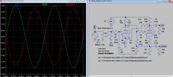
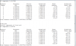
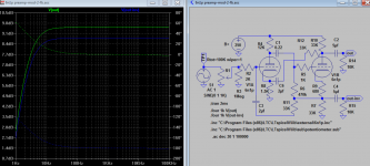
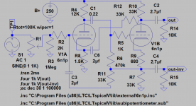
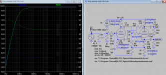
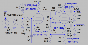
For the gain you requested I need to adjust plate res to 12K from 33K and cathode 680 to 1.5K with 33K feedback. Because of feedback, the output remains quite constant for load as low as few K. Distortion is < 0.05%. If you have low load make sure you have enough capacitance for C2 output coupling capacitor say 3-5uf, see attach snapshots.
Yes, you can float the heater, the amount will depend on noise level on your system, 60V should sufficient and above the noise level, there may be hum other than through heater, maybe good to use ground lift device too.
Attachments
Last edited:
That looks pretty good, thanks!
The first tube is biased pretty hot, or am I thinking that wrongly?
Can you help with the DC voltages at the plate and cathode of each tube? It would be nice to have when I build it and something blows up
Edit: Sorry, just wanted to figure why the -out is a little less than +out, and whether we can balance that by using a different plate R on the splitter? I would definitely want to use balanced output at some point.
Last edited:
That looks pretty good, thanks!
The first tube is biased pretty hot, or am I thinking that wrongly?
Can you help with the DC voltages at the plate and cathode of each tube? It would be nice to have when I build it and something blows up
Edit: Sorry, just wanted to figure why the -out is a little less than +out, and whether we can balance that by using a different plate R on the splitter? I would definitely want to use balanced output at some point.
No problems. Not quite hot @0.62W power dissipation.
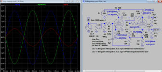
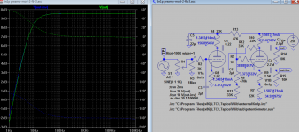
I raised the cathode resistor R9 to 3.9K from 680 to get exact balance, and output is taken out on top of cathode resistor R9. So you can adjust R9 in actual circuit to perfect balance. It's a little more complicated than ordinary phase spliter because of feedback, but it does allow adjustment. But distortion goes up a bit to 0.17% from 0.05% though because loss of current drive for 10K load. Maybe spliter arms res can be changed to suit, I see if i come up with a better distortion figure.
Attachments
Last edited:
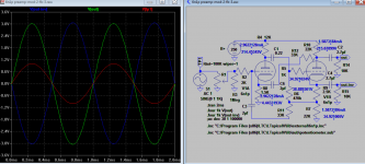
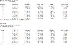
Distortion improved to ~0.06% when anode res R10 and cathode res R7 are both 22K and R9 is 2.5K for perfect balance. The power dissipation is 2.7W, think that about best of all now.
Edit: You are right the 1st tube is too hot, sorry i miscalculated it, here is the cool one
Edit: You are right the 1st tube is too hot, sorry i miscalculated it, here is the cool one
Attachments
Last edited:
Fantastic work, thanks for the effort! The odd orders are lower than even order in this iteration in spite of the overall number being higher, should be a nice little pre
2.5W is too far out of tube spec I think the plate is rated to 2W max for each tube half. But I get 0.62 on V1A and .3W on V1B. Or is that the dissipation on V1b alone during signal swings?
I've also heard of folk reducing the plate resistors (deliberate imbalancing of the cathodyne) to restore balance in the output. The difference is a normal part of the Cathodyne apparently :|
I don't think the load is 10k, maybe 22k per half on the amp side and if I add no additional output balancing maybe that is what it will be. I usually don't like floating the output in any case, so maybe 220k pulldown + 22k amp load.
Terry, I don't think this will be made on a PCB in my case. Plus I don't have your skill in making boards I'll be going retro on this one!!
Edit: got it, we have to drop the plate supply on first tube.
All looks good, hopefully should have this running over the weekend with scrapyard parts before I do the finals
Last edited:
Fantastic work, thanks for the effort! The odd orders are lower than even order in this iteration in spite of the overall number being higher, should be a nice little pre
2.5W is too far out of tube spec I think the plate is rated to 2W max for each tube half. But I get 0.62 on V1A and .3W on V1B. Or is that the dissipation on V1b alone during signal swings?
I've also heard of folk reducing the plate resistors (deliberate imbalancing of the cathodyne) to restore balance in the output. The difference is a normal part of the Cathodyne apparently :|
I don't think the load is 10k, maybe 22k per half on the amp side and if I add no additional output balancing maybe that is what it will be. I usually don't like floating the output in any case, so maybe 220k pulldown + 22k amp load.
Terry, I don't think this will be made on a PCB in my case. Plus I don't have your skill in making boards I'll be going retro on this one!!
Edit: got it, we have to drop the plate supply on first tube.
All looks good, hopefully should have this running over the weekend with scrapyard parts before I do the finals
Ya you right again I keep thinking it is 6sn7 or 5687!. If the load is not 10K than distortion is better, you can keep earlier 33K res arms and drop the plate supply voltage so V1A also < 2W. See my previous last attachment for V1 adjustment.
Thanks. I have heard it is best when you run the tube a little hot:
Tube Tester Files - 6N1P - 6H1?
I will build it out soon with your last schematic (reduced B+) and see what happens. Tubes are cheap enough that the first one can be guillotined if needed.
Tube Tester Files - 6N1P - 6H1?
I will build it out soon with your last schematic (reduced B+) and see what happens. Tubes are cheap enough that the first one can be guillotined if needed.
Thanks for the advice guys, it is singing.
Hi Terry,
I have biased the tube 6N1p too hot, just wonder what it does to ECC88 with zero in cathode res. on original circuit. What cathode res you used, not 200 ohms is it?
http://www.diyaudio.com/forums/atta...ube-ss-preamp-apex-counterpoint-part-list.jpg
Here is the parts list I used. I fed the heater directly from the 6.3vac winding from the transformer. The L7805 ran too hot if I used it to feed the heater.
Edit ; I misunderstood. I used 100R for the cathode resistor with the 6n1p. For the ECC88 I used none.
Here is the parts list I used. I fed the heater directly from the 6.3vac winding from the transformer. The L7805 ran too hot if I used it to feed the heater.
Edit ; I misunderstood. I used 100R for the cathode resistor with the 6n1p. For the ECC88 I used none.
Last edited:
http://www.diyaudio.com/forums/atta...ube-ss-preamp-apex-counterpoint-part-list.jpg
Here is the parts list I used. I fed the heater directly from the 6.3vac winding from the transformer. The L7805 ran too hot if I used it to feed the heater.
Edit ; I misunderstood. I used 100R for the cathode resistor with the 6n1p. For the ECC88 I used none.
Ok good. I have reviewed the sch again and find both are not too hot < 0.5W heat. But with zero bias on ECC88, I find it has very high distortion even at 1mV, about 0.9%, and >6% at 100mV input. But if 100 ohms cathode, it's as good as 6N1P. Just a note for those readers on this thread.
Ok good. I have reviewed the sch again and find both are not too hot < 0.5W heat. But with zero bias on ECC88, I find it has very high distortion even at 1mV, about 0.9%, and >6% at 100mV input. But if 100 ohms cathode, it's as good as 6N1P. Just a note for those readers on this thread.
Are you saying it would be better to add a cathode resistor to the ECC88 circuit?
Are you saying it would be better to add a cathode resistor to the ECC88 circuit?
Yes, plus 100u bypass cap.
Distortion improved to ~0.06% when anode res R10 and cathode res R7 are both 22K and R9 is 2.5K for perfect balance.
By "perfect balance" did you mean the same plate current through both V1 and V2? Or did you mean output signal balance (inv vs non-inv)?
That's a really clever way of applying nfb to a cathodyne. Did you check for inverted vs. non-inverted output signal balance? Does the balance between inv and non-inv outputs stay good as the splitter approaches overload?
Also, how did you choose the resistor values for the negative feedback loops?
- Status
- This old topic is closed. If you want to reopen this topic, contact a moderator using the "Report Post" button.
- Home
- Amplifiers
- Tubes / Valves
- 6n1p preamp schematic