Back when I had a hamshack set up (with 12AT7 mixers in the receivers!), I ran the whole setup through a big variac with a 5" expanded range meter centered on 120VAC built into the case as found at a hamfest. The meter covered about 105-130VAC over a few inches of scale.
I used this because the heaters in 1950s communications radios would run too high on my 123-125V line. They were usually designed for 110V or 115V nominal.
I seldom saw that needle wiggle and I don't think it was well damped. Once in a while I would see a spike that bounced the needle off of the top stop, which was scary. I installed a well protected power strip with MOVs.
My intuition would be to blame LF wobble on inferior decoupling, but the right regulation scheme would solve both AC variation and decoupling issues in one blow.
Noise is less important than PSRR and Zout when it comes to a listener's assessment of quality.
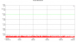
It's "illuminating" to look at the FFT of a tone coupled to a power supply rail -- say a few mV. You get a picture of Zout and THD created by the power supply.
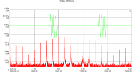
As an example, see the attached. This is a view of a 150V supply, DC loaded only, and additionally loaded with a tone burst drawing a few mA simulating a musical signal.
The supply is pretty quiet as it is, but once the burst load is on, it looks much different, although still very low.
What that does to the audible quality of course depends on a lot of other factors, but the effect is clear.
Jan
Attachments
How did you do the plot overlays like that? Very high information density!
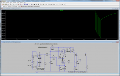
The dScope can show time domain and frequency domain plots in the same graph. If you think about it it really is a no-brainer - it's just pairs of X-Y points of course - but I don't think others have thought about it. Not even AP as far as I know ;-)
Jan
I have seen what looks like (temporary) DC level shfts on the output of my 5-20 amp. Subsonics can get through an OPT, even though they will be attenuated. The basic idea is that you don't want big signals you can't hear messing around with the bias of stages carrying signals you can hear. This includes the OPT and the speaker. A line stage transformer may pass subsonics even better, as it is likely to have a wider bandwidth than a typical OPT.
It certainly does in the UK. I would be surprised if it did not do the same elsewhere. When I found this stuff on my amp output I was puzzled about where it came from, until I noticed it was correlated with shifts in the HT rail voltage - which can only come from mains variations.
This correlates extremely well with my experience as well, although I have observed that transformer coupling reduces the phenomena considerably as compared to RC coupling. Most of the transformers I use are not significantly better on the bottom end than my OPTs, however they are generally considerably more extended on the top end.
Are you attributing this VLF signal to AC line variation? I'm surprised that line voltage varies that way but it might. I think DC pulses on the line, which are apparently quite common and introduced by asymmetrical loads somewhere on your utility branch could zap your transformer operation, especially with toroids, creating a similar effect.
And maybe 1hz response is just a bit excessive?
I have had LF instability/speaker pumping in amps but never blamed the AC line.
Yes, I do attribute this to the AC line as it correlated perfectly with variations in the unregulated B+ supply, although it was very attenuated in comparison, but not enough to prevent the problem it caused. (I observed [still do] as much as a couple of volts of variation due to this cause on a B+ of 400V, this was suppressed by more than 60dB at the output of the regulator but was still enough to cause mischief with those amps.) Oddly enough line voltage wander can sometimes cause VLF problems in high gain amplifier circuitry running on unregulated filament supplies, I admit that I rarely bother to regulate those filament supplies but in a few instances where I did the behavior was significantly better. Choosing somewhat smaller RC coupling time constants within reason is a pretty effective way of dealing with it.
The low cut off frequency was quite deliberate as I coming from the solid state world and was trying to minimize phase shifts at the low end. I no longer try so hard, but for RIAA accuracy at the bottom end relatively low frequency cutoffs are still required. (I am not a fan of IEC equalization!)
My current designs are considerably quieter than those early designs and share very little in common with them other than oddly enough the basic voltage regulator topology which I still use with some additional refinements..
I have horns on mids and highs and diy Onken bass cabinets for the bottom, efficiency is >100dBspl/w/m so the electronics here have to be extremely quiet. I've managed that, everything but the GM70 power amps use regulated B+.
It may be that you happen to live somewhere with extremely well regulated mains voltage. I do not. Note that "inferior decoupling" will pass a variation which better decoupling would further attenuate, but the variation comes from somewhere. A transformer, rectifier and reservoir cap do not spontaneously generate output voltage variations themselves.Joe Roberts said:My intuition would be to blame LF wobble on inferior decoupling
Jan, interesting plots! And nice tools! ;op
Do you have any theory of the mechanism in play which generates those modulated spikes?
As you mention, they are low level but the pattern is intriguing.
DF96, I recently moved to downtown Washington, DC. No telling how bad the AC is around here. Probably horrible beyond words. I should probably think about that more and take a look. Back in Austin TX, I was on a solely residential spur and life was pretty good.
On the variation in B+, the only other explanation that leaps into mind is oscillation beyond frequency of the scope at hand causing episodic variations in current through the PSU...but I'm grasping here. If the mains is screwy, that is obvious cause for concern.
Interesting points here, validating my current interest in good preamp regulation schemes.
Jan, interesting plots! And nice tools! ;op
Do you have any theory of the mechanism in play which generates those modulated spikes?
As you mention, they are low level but the pattern is intriguing.
Joe, not saying I can precisely reproduce the theory but what you see are the frequencies that are present in the burst signal. You see the frequencies spaced 1 kHz apart as that is the repetition freq of the burst. The repeating pattern is determined by the burst signal frequency (10 kHz) and the duty cycle.
I think if I would do an FFT of the burst you would see the same pattern but different levels.
The height of the spikes is determined by the load current resulting from the burst signal through the supply Zout.
Jan
Last edited:
As an example, see the attached. This is a view of a 150V supply, DC loaded only, and additionally loaded with a tone burst drawing a few mA simulating a musical signal.
It would be interesting to extend this test with repeated bursts of a few milliseconds of the pluck of a bow, the impulse from a trumpet, or Joan Sutherland mashing her vowels and consonants ... I can do this on the AP.
There seemed to be a weak correlation between LF PSRR and perceived sound quality. This could be extended to subsonics -- vide the discussion of subsonic flapping elsewhere.
5pcs DC DC 3A Converter Adjustable Step Down Power Supply Module Replace LM2596 | eBayDC heater regulator is mandatory, and the smart trick used by SY with +/- 6V3 to improve common mode rejection, I strongly dislike LM317/337, so a regulator a la Walt Yung/Jan Didden seems to me a better choice.
No offence intended SY.
works like charm. you can add filter, if you want http://www.tme.eu/u/produkt-tygodnia/x37-02.jpg
isolated with tape, and pressed against metal, will keep it cool (5V 2A tested)
5pcs DC DC 3A Converter Adjustable Step Down Power Supply Module Replace LM2596 | eBay
works like charm. you can add filter, if you want http://www.tme.eu/u/produkt-tygodnia/x37-02.jpg
isolated with tape, and pressed against metal, will keep it cool (5V 2A tested)
Thanks for the info, anyway this kind of things are impossible to obtain because here it is forbidden import, even for such small things.
I must build my PSUs with available parts here.
I must to claim to my parts provider for 15 fake MOSFETs, err, 14 counting the one broken with a hammer, just to verify that it is fake after measure gate-source capacitance, a half of that on datasheet.
farnell, digikey,mouser?
I cannot to talk about politics, so most of you must think that I am a kind of alien, but believe me, import is forbidden here, maybe next year...

Hi,
Nice work, Jan.
Shows how even the best PS ends up modulated by the signal.
n previous work posted and publicized here I deliberately opted for dedicated well regulated series supplies for each stage left and right channel of a stereo phono preamp for there's not only just PS intermodulation but also interstage and interchannel PS modulation.
So, dual mono and each stage well regulated with its own dedicated powertrannie etc.
Net result? Beats the hell out of anything commercially available and it was still designed to be "affordable".
And yes, I'm sure it can be pushed further no end.
As a side remark" I notice most US based guys are accusing VR valves of being to noisy to be any good in a serious reg. Yet the European counterparts are much more quiet and stable. Up to the point that, when well buffered with massive caps and a reasonable PSSR at the amplifying stages, PS noise becomes a none issue.
I keep to be amazed though by the sonic impact of a PS on an amplifying stage.
That said, series or shunt, for a phono pre, I can't see how you could do without either of them. A straight LCR filter? No way Jose.
Just like KevinkR, I stick with a cascaded error amp (I use VR tubes instead of zeners, see above) and stick a couple of big caps in parallel after that.
Anything you change to that regulated PS is still audible. A valve, a cap. You hear the change. Which is surprising as on paper you shouldn't.
If pushed into designing the ultimate phono pre I'd still go to route described above but use cascaded amplifying stages coupled directly into White cathode followers. Yet another audiophile nono......
Enough said,
Can we please talk valved regs as from now on? Series or shunt or a combination of both, whatever They're so much fun really.Not to mention valve rectifiers....
Cheers,
As an example, see the attached. This is a view of a 150V supply, DC loaded only, and additionally loaded with a tone burst drawing a few mA simulating a musical signal.
The supply is pretty quiet as it is, but once the burst load is on, it looks much different, although still very low.
What that does to the audible quality of course depends on a lot of other factors, but the effect is clear.
Jan
Nice work, Jan.
Shows how even the best PS ends up modulated by the signal.
n previous work posted and publicized here I deliberately opted for dedicated well regulated series supplies for each stage left and right channel of a stereo phono preamp for there's not only just PS intermodulation but also interstage and interchannel PS modulation.
So, dual mono and each stage well regulated with its own dedicated powertrannie etc.
Net result? Beats the hell out of anything commercially available and it was still designed to be "affordable".
And yes, I'm sure it can be pushed further no end.
As a side remark" I notice most US based guys are accusing VR valves of being to noisy to be any good in a serious reg. Yet the European counterparts are much more quiet and stable. Up to the point that, when well buffered with massive caps and a reasonable PSSR at the amplifying stages, PS noise becomes a none issue.
I keep to be amazed though by the sonic impact of a PS on an amplifying stage.
That said, series or shunt, for a phono pre, I can't see how you could do without either of them. A straight LCR filter? No way Jose.
Just like KevinkR, I stick with a cascaded error amp (I use VR tubes instead of zeners, see above) and stick a couple of big caps in parallel after that.
Anything you change to that regulated PS is still audible. A valve, a cap. You hear the change. Which is surprising as on paper you shouldn't.
If pushed into designing the ultimate phono pre I'd still go to route described above but use cascaded amplifying stages coupled directly into White cathode followers. Yet another audiophile nono......
Enough said,
Can we please talk valved regs as from now on? Series or shunt or a combination of both, whatever They're so much fun really.Not to mention valve rectifiers....
Cheers,
Hi,
Forgot to mention for those still stuck in books and theory: a dual triode is not the same as a twin triode.
Futhermore, the best matched twin triode valves are only matched on the testing machine, after that they won't stay matched in any circuit for long.
Paralleling those twins still needs individual cathode Rs to balance currents and so on and even that doesn't guarantee true balance at all in the long run.
Not that it always matters but I wouldn't dream of designing anything count on that to make magic......
Cheers,
PS: Same thing for PP amps. No need for absolute balance unless you're a zero distortion freak and then some.
- Status
- This old topic is closed. If you want to reopen this topic, contact a moderator using the "Report Post" button.
- Home
- Amplifiers
- Tubes / Valves
- tube regulators