Hi there
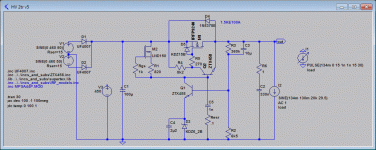
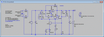
I've been searching for a HV regulator design to suit me for quite some time but was never quite happy with any of the stuff I found. All appeared to be wither limited in performance or overly complex, so I went ahead and came up with the attached design. My requirements were:
After trying many approaches, some more exotic than others, I returned to a variation of the plain 2 transistor regulator, with some twists. One is to feed the error amplifier and pass element from a CCS, and the other is to employ a compound bjt / mosfet pass element.
The shown design puts out 400V with about 405V~480V on the input. Add a a trimmer at R2 to adjust the output voltage.
MPSA44 also works in place of the ZTX458. For higher voltages, replace Q1 with a higher voltage BJT. Or stack some bypassed zeners on top.
I did not build the regulator yet, but probably soon will. I guess I will have to keep wires short to prevent oscillations. Any other pitfalls?
I've been searching for a HV regulator design to suit me for quite some time but was never quite happy with any of the stuff I found. All appeared to be wither limited in performance or overly complex, so I went ahead and came up with the attached design. My requirements were:
- Excellent line and load regulation over the whole audio band.
- Using easily available COTS parts.
- Discrete design preferred.
- Easy to build.
- 400V minimum, better 500V+. 200mA avg. 400mA peak minimum current.
- Broadly temperature compensated.
After trying many approaches, some more exotic than others, I returned to a variation of the plain 2 transistor regulator, with some twists. One is to feed the error amplifier and pass element from a CCS, and the other is to employ a compound bjt / mosfet pass element.
The shown design puts out 400V with about 405V~480V on the input. Add a a trimmer at R2 to adjust the output voltage.
MPSA44 also works in place of the ZTX458. For higher voltages, replace Q1 with a higher voltage BJT. Or stack some bypassed zeners on top.
I did not build the regulator yet, but probably soon will. I guess I will have to keep wires short to prevent oscillations. Any other pitfalls?
Attachments
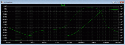
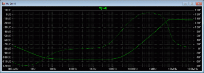
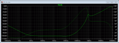
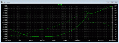
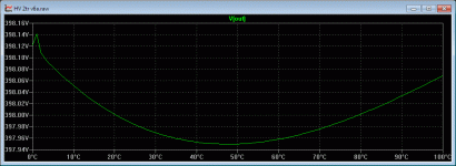
Some more diagrams on performance
- line regulation
- load regulation
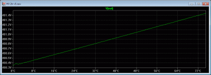
- temperature behaviour
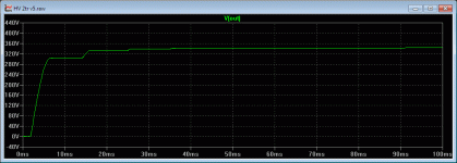
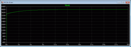
- startup
- startup, first 100ms
Attachments
I use something fairly similar to regulate G2 voltage in my amp, and I'd say its pretty much reliable, and even it doesn't heat up much. My regulator is adjustable, I've got a trimpot between R2 and R3.
One question: why do you need C3/R7?
C3 is a speed up cap. It drives the base of Q1 with low impedance (R7) instead of high impedance (R3), massively enhancing the regulation.
R7 is needed "only" to limit Q1 base current during startup.
EDIT: I just noticed the schematic in #4 is defective after adding the protection diode D6. Please add another current limiting resistor 18K~22K between the collector of Q1 and base of Q2.
Should work again then without frying Q1 during startup.
Last edited:
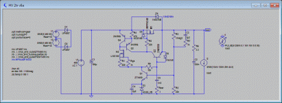
Just wanted to post the latest incarnation of this regulator. Added protections and a dual ccs load for another -20dB load regulation..
See attached pics:
Next addition would be a foldback current limiter.
See attached pics:
- Schematic
- -100dB line regulation over the audio band
- -120dB load regulation (bass and mids), dropping to -100dB for the treble
- <1% temp variation 0°C~100°C (here 200mV for 400V offload)
- Low control current waste, ~1.3mA or ~0.5W at 400V offload
Next addition would be a foldback current limiter.
Attachments
Some suggestions:
You can further improve ripple and load rejection by supplying the reference zener from the regulated side. 100 dB is good but not really low noise (10 V rms on the supply became 0.1 mV RMS noise)
A differential amp and a bandgap reference may improve noise and temperature coefficient. Zeners at such low currents are rather noisy.
The startup behaviour is very slow.
What is the advantage of using mosfets instead of bjt?
Stability may be better by using emitter followers instead of the sziklay pair.
This may not be a problem as the circuit has not much loop gain.
Regards,
Udo
Hi Udo, thanks for your suggestions, some comments
80% of target voltage is reached after 15ms
90% of target voltage is reached after 1.7s
The circuit is stable after ~45s.
Also, the Vgs provides a nice little headroom for the ring-of-2 CCS to work within.
The CCS supplies feed the circuit with over 140dB rejection, even from the unregulated side. There's no improvement to be had by going to the regulated side.You can further improve ripple and load rejection by supplying the reference zener from the regulated side.
A zero tempco (bandgap) reference does not help. We still have the BE junction tempco of Q1. The 6.2V zener tempco cancels it out nicely. The zener is bypassed to kill the noise.A differential amp and a bandgap reference may improve noise and temperature coefficient. Zeners at such low currents are rather noisy
D4 provides a quick start,The startup behaviour is very slow.
80% of target voltage is reached after 15ms
90% of target voltage is reached after 1.7s
The circuit is stable after ~45s.
It's easier to drive.What is the advantage of using mosfets instead of bjt?
Also, the Vgs provides a nice little headroom for the ring-of-2 CCS to work within.
In simulation at least, the circuit is stable into resistive and ccs loads. Big capacitances may be a little problematic, I'm still investigating further. It does survive all kinds of nasty pulses without going into oscillation, though.Stability may be better by using emitter followers instead of the sziklay pair.
Last edited:
Hello,
At least in simulation of a 50 volt regulator i easily got 140 dB of line rejection if i put the reference on the regulated secondary side.
And cost is marginal. Line rejection is important for single ended preamps which do not have much line rejection by themself.
If the current source has 3 Mohm impedance and the zener reference has 30 Ohm, this
is only 100 dB line regulation. Not counting capacitive feedthrough.
Yes, the bandgap needs a (discrete) diffamp for good tempco. It is easy to get 0.1% precision with a bandgap without adjustments.
The Zener gives 2-5% precision.
Startup should be faster than 1 second for a good regulator, in my opinion. This should be easy as the regulator has no big output caps.
I looked through some high voltage datasheets and the SOA / $ seems to be better for mosfets.
BTW, the main Mosfet should withstand at least 480 volts in your circuit (startup and transient pulses). 200 volts seems too risky.
CAT-I must withstand 1500 volt transient pulses without damage or fire risk.
Stability gets a problem if you want good line regulation as this implies high feedback.
The emitter follower has an advantage. It uses only NPN (NMOS) parts and these are more common at higher voltages.
And the output impedance stays low up to very high frequencies (no feedback).
For such high voltage i would add a dedicated fuse and a (inrush) current limiter to ease safe operating area.
Nevertheless your regulator will work very well, but improvements are always possible
Udo
Last edited:
It's line and load regulation are only around 40~60dB.Why not use the SuperTex (DiodesInc) LR8N3 to drive the gate? Eliminate Q1,2,3 M2 etc. [...]
It's line and load regulation are only around 40~60dB.
I have charts like these
http://linearaudionet.solide-ict.nl/sites/linearaudio.net/files/V4 JW F5.pdf
For the LR8N3, Maida, 3 transistor HV designs (Morgan Jones), and one of my faves, "The Last PAS"...but they are 500 miles away back in the lab! Line Rejection, Output Impedance and Noise. It's not easy to perform these tests with a high degree of precision at high voltages.
The 3 transistor regulator with the depletion mosfet current source is a great idea.
- Status
- This old topic is closed. If you want to reopen this topic, contact a moderator using the "Report Post" button.
- Home
- Amplifiers
- Tubes / Valves
- HV regulator design - opinions?
