This should be another 'advanced' thread on CFB and nested driver stage feedback. I like your drawing. So far I am only trying to develop the driver stages and regulated power supplies is next, maybe one day I will build your design.Some would say the Mac is over-complicated. My opinion is that they didn't really fix the right things. Here is a circuit that can equal the Mac's performance using cheap Edcor OTs.
And it does fix the right things: No tube matching required because of the DC balance control. An AC balance control would also be used in the prior driver stage. The driver stage is not shown here, but would use a variation on the RCA 50 Watt Schade design (below). Which can provide the same level of local (partial Fdbk, ie OT out of loop) error correction as the Mac.
Local Fdbks would come off the bottom OT cathode connections (crossed Fdbks) so as to reference ground (unlike the usual Schade Fdbks that reference from B+). This eliminates power supply ripple from the local Fdbks and more closely couples cathodes (low Z) to the output windings, since UL taps are generally closely coupled to the secondary for UL Fdbk purposes. The plate outputs on the other hand are left as high Z, so as to couple through OT leakage L of the outer winding sections transparently. BOTH UL winding sections of BOTH OTs are used by EACH cathode, reducing leakage L to the secondary by 4X for the CFB winding part. (this is way better than the Mac design)
-----------------------------------------------------
Also, a note on using ferrite beads for anyone venturing there. You need to check that the bead material chosen can handle the DC circuit current without saturating. Most beads around these days are low permeability for SS use, so won't be a problem. But one could optimise for low tube currents with higher perm. material.

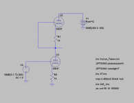
goldenbeer, would this attached schematic be properly balanced?
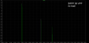
I don't know how to balance it more. I even took the load out; this increased the output from 32 VPP to 36 VPP. Please advise.
As for my conclusions:
1) Do you disagree that the SRPP has significantly higher output impedance (regarding my conclusion on it's drive capability)?
2) Do you disagree it is not without problems to make the SRPP actually balanced, i.e. find matched triodes in real life? Or, have them age exactly the same?
3) Do you disagree that a triode with evenly spaced curves in it's area of operation that is to be used will perform with lowest distortion using a load line that is approaching horizontal?
Attachments
An amplifier should be as simple as needed an no simpler. Sacrificing performance in the name of a lower part count only makes sense if you are trying to bring your product to market.
Would you consider this amp simple or complex?
What about this one?
One last one for good measure
Would you consider this amp simple or complex?
What about this one?
One last one for good measure
JZatopa, all ridiculously simple compared to the MC-275. The math needed to calculate cathode feedback with partial nfb in the driver stage is beyond me.
Audio research is even more complex than McIntosh. I spent 2 days trying to figure out why they had two long tail pairs in a row mixed with cathode followers with some weird feedback loops that didn't make sense. I guess they were trying to cancel some of the phase splitter coloration by removing symmetrically the error with local feedback.
If you want to look to gears that are simple, look at Air tight, sky high prices, 5 stars review, and I trust the reviews on it. I think one of their secret is to use big *** output transfo , another manufacturer would use a 25 watts rated for EL34, they use a 75 watt one.
Last edited:
goldenbeer, would this attached schematic be properly balanced? [...] Please advise.
Please read up some fundamentals about the SRPP, like merlin's 2 part article.
I attached one possible balanced circuit for the 6SN7. H2 (and all even order H), and THD, are vastly lower than for the mu follower. H3 (and all odd order H) is obviously still higher though.
1) Do you disagree that the SRPP has significantly higher output impedance (regarding my conclusion on it's drive capability)?
Output impedance of the SRPP is a pretty moot point, because it only works with exactly one optimum load impedance anyways. It's drive capability is not too bad, certainly much better than resistor loaded grounded grid stages.
2) Do you disagree it is not without problems to make the SRPP actually balanced, i.e. find matched triodes in real life? Or, have them age exactly the same?
Concerning matching and ageing of triodes, the SRPP is no worse or better than the LTP, a usually pretty highly regarded circuit in terms of distortions and fidelity.
3) Do you disagree that a triode with evenly spaced curves in it's area of operation that is to be used will perform with lowest distortion using a load line that is approaching horizontal?
You could devise some exotic active load circuits where the load line is actually slanted upwards, giving even lower distortions than horizontal.
The question is, if it's worth the effort.
Attachments
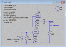
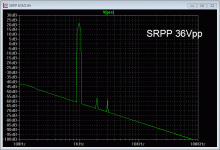
I attached one possible balanced circuit for the 6SN7. H2 (and all even order H), and THD, are vastly lower than for the mu follower. H3 (and all odd order H) is obviously still higher though.
While I agree that your SRPP is the proper way to do it, SRPP sims are very optimistic due to the perfect matching of the tubes. I've found mu-followers sims to translate much better to real world measurements. So I'm a bit doubtful about that "vastly lower" thd in practice.
While I agree that your SRPP is the proper way to do it, SRPP sims are very optimistic due to the perfect matching of the tubes. I've found mu-followers sims to translate much better to real world measurements. So I'm a bit doubtful about that "vastly lower" thd in practice.
The problem with the SRPP, and what I didn't mention above
, is of course that, contrary to the LTP, the even harmonic cancellation highly depends on the load impedance, and hence the Rp of the tube as well... and by that I mean not only matching Rp between the two triodes, but sample to sample variation from tube to tube.You can overcome this by making the load resistor variable and trimming it for lowest thd for every actual bulb you're using, but of course it's cumbersome and rarely done. But if you do, reality will match with sims.
Anti-Triode derived version of SRPP. R3 develops bias V for top tube. R5 develops AC drive for top tube. Voltage drop across R3+R4 stays close to constant as currents of top and bottom tubes are kept complementary (acting like a CCS or LTP tail)
Normal Anti-triode mode would use a high gm device (Mosfet or depletion mode Fet) for the top device, with an appropriately reduced R5 drive, to maintain complementary currents in R3 and R4. (Mosfet version uses a Zener or equiv. in the gate lead to bias it up + a high R gate pull-up instead of R5, R3 and R4 values can then be chosen for just current sampling purposes.) Top device can be further gm enhanced by additional device(s) too.
Normal Anti-triode mode would use a high gm device (Mosfet or depletion mode Fet) for the top device, with an appropriately reduced R5 drive, to maintain complementary currents in R3 and R4. (Mosfet version uses a Zener or equiv. in the gate lead to bias it up + a high R gate pull-up instead of R5, R3 and R4 values can then be chosen for just current sampling purposes.) Top device can be further gm enhanced by additional device(s) too.
Attachments
Last edited:
R4 +R5 are the load for the gain of the lower triode, you said R5 develops AC drive... I would say R4+R5, I need more explanation to understand why it is important to balance V constant of R3 and R4, it looks obvious that the AC signal will be equal but I don't see the utility of it.
IF the AC currents (driving the load Rl) through R3 and R4 are complemtary, then the V drop across R3+R4 is constant, so this has no effect on the AC drive signal of the top device (to 1st order) through C2 (the top device AC drive signal being the voltage variation across grid to cathode of the top device). Ideally, R5 derives exactly the AC drive signal needed by the top device, like an SRPP, for complementary operation.
Similarly for an LTP, the tail voltage would remain constant if the two active devices were perfectly linear with equal complementary drives. But like the LTP, when the devices do not sum to constant current, the tail alters the voltage slightly to fix that. R3+R4 do the same thing here. Any imbalance of current complementarity alters the V drop across R3+R4 in such a way as to correct the AC drive to the top device through C2.
Example:
If the top device does not turn off sufficiently to match the turn on of the bottom device, then the V drop across R3 will not cancel the V increase across R4, so the net effect is for V R3+R4 to increase, turning the top device off some to correct. Similarly for the opposite case.
A high gm device up top of course makes this correction scheme work really well, and was the modus operandi of the original "anti-triode" totem pole design. (there are LTP like "anti-triode" designs as well) The anti-triode arrangement prevents the 2nd device from cancelling the even harmonics of the 1st (driven) device by strict current complementarity, and the higher the gm of the slaved device, the better it works at that. So a high gm device up top (or slaved in LTP form) will give a preserved SE signature of the driven tube. This allows a P-P stage to emulate SE without all the associated SE problems (ie, OT gap). And gives 2X the power of the single SE tube besides.
Last edited:
For an anti-triode like SRPP totem pole setup, mentioned above, the top tube is just acting to double the effective AC current into the load. And it does that without imposing any cancelling even harmonics from the top tube. So it should have a spectrum similar to the bottom tube loaded by 2X (the Ohms) of the actual load R. (bottom tube only having to supply half of the AC load current) Similar to class A P-P except the even harmonics are left in now.
My old computer crashed some while back with actual FFT measurements from years ago.
Since the finite gm of the top device limits the fine grained accuracy of the scheme some, you might see a couple dB less even harmonics than expected from the loaded bottom device alone, when using a tube up top. Higher gm up top will preserve more % of the even harmonics. (Obviously this scheme is NOT intended to provide the absolute lowest distortion, like a Mu follower. It was intended as a P-P output stage that would give SE results.)
By the way, MJ's book, 4th edition, provides some info on Mu follower versus SRPP on page 128. You might want to check out the Beta follower too.
Last edited:
- Status
- This old topic is closed. If you want to reopen this topic, contact a moderator using the "Report Post" button.
- Home
- Amplifiers
- Tubes / Valves
- Simplicity or complexity?