I know there is a ton of documentation on these tubes being tortured, but has anyone run them in Class A? I've finally run my stash down to a few parts, and I have 8 6CB5As, a pair of 1.5k Sowters, and a pair of big ~280-290V power iron. I'm thinking of a low B+ and full class A.
Any experience?
Thanks!
Any experience?
Thanks!
Something kind of like the OddBlocks here:
http://diyaudioprojects.com/Tubes/5...51-SRPP-KT88-Push-Pull-Tube-Amp-Schematic.png
http://diyaudioprojects.com/Tubes/5...51-SRPP-KT88-Push-Pull-Tube-Amp-Schematic.png
I made an oddwatt but with 1625s. I think I got 25 watts out or so. I'm trying to make a PPP 6GB5 now, I should be able to get 130 or so out, with a B+ of 400. What is the real plate dissipation of a 6CB5? 6.3 volts and 2.5 amps of filament it should be massive, at least your filament transformer is gonna be.
Nice! The 6CB5A is rated at 26W plate dissipation. I was thinking PPP class A. Hoping for 60-80W.im also not sure the driver topology for the Oddwatt will drive PPP to full power.
My power iron has at least 12A of heater each.
This looks do-able. The 1K5 OPT looks good here, somewhat less output, but lower distortion as well being that it's a bit on the large side.
As for the drive, I really don't like using 6SL7's as SRPP's, being that it's a low current, high gain type. It shouldn't have problems with drive, so long as you can get the Ipq of the 6SL7 above 1.2mA or so. Still, I'd prefer using the two sections in parallel, with an active plate load rather than an SRPP.
You could also include a source follower as a grid driver. That'll get you more than enough grid drive, as pents aren't hard loads if you keep 'em out of grid current.
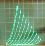
Attachments
Awesome Miles!
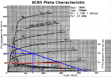
Looking at the graph, is that biased at 100mA per 6CB5A to keep them in class A?
Yes, each final gets 100mA of Q-point plate current, so a quad would pull 400mA total.
Should I use a separate CCS on each cathode?
The Oddwatt doesn't, however, you can AC couple and still get the same self splitting final with a CCS on each cathode. This has the advantage of allowing for easier plate current balancing, but it does put some large electrolytics in the signal path.
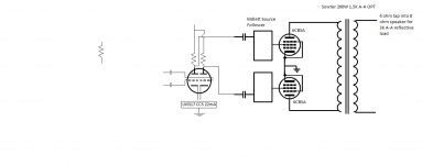
Got a solid source follower schematic you know of as an example?
Yeah, like this. The source follower doesn't need much more than a Q-point current of 20mA or so. May not even be necessary as pents operating as pents aren't a difficult load. It does require a negative rail to set the grid bias unless you AC couple.
Attachments
Pete Millett has a nice little source follower board for $15 that has two followers on each board. In PPP operation, do you need a follower on each tube, or will a follower drive two screen grids?
Using screen drive, wouldn't it make a bit more power than class A if I went AB2?
Using screen drive, wouldn't it make a bit more power than class A if I went AB2?
I think George (Tubelab) got around 120 - 150 Watts in AB2 screen drive with a pair of 24 Watt 6HJ5 into a 3.3K OT, so the 26 Watt 6CB5A should handle that. 100 Watts out might be a more relaxed figure for reliability for a pair.
I would think that some Mosfet would be able to drive two tube screen grids readily. Although a quad of 6CB5A may be a bit too much output power. But they fit the Sowter at 1.5K. Higher plate voltage (and a higher primary Z) will reduce the screen current some, and allow some boost of power output.
Going more class A (Ab) to reduce crossover distortion, would also bring down the available power output significantly. But screen drive seems to allow closer to class B operation.
Last edited:
I've got a bit of overhead with these Sowter outputs. They are rated at 200W.
It would be nice to find a midget that will drive each pair of tubes without needing two boards.
Regarding the output power, I'd rather have something that does not push the outputs to the limits. Just a bulletproof amp that puts out a good amount of power.
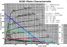
I believe Miles, a while back, pointed out that the 6CB5A is ideal into a 2.56K anode load in PP.
It would be nice to find a midget that will drive each pair of tubes without needing two boards.
Regarding the output power, I'd rather have something that does not push the outputs to the limits. Just a bulletproof amp that puts out a good amount of power.
I believe Miles, a while back, pointed out that the 6CB5A is ideal into a 2.56K anode load in PP.
I believe Miles, a while back, pointed out that the 6CB5A is ideal into a 2.56K anode load in PP.
I ran some loadlines for the 6CB5, but that was a Class AB loadline, not a Class A. A single pair in Class AB does ~65W with reasonably low h3 estimate. In the OP, deicide asked about Class A loadlines.
I'd prefer a single pair in 'AB myself. These TV HD types work quite well that way, and I did a project with the lower power 6BQ6GA that sounds really good. That was a "junk box" design that worked really well with an OPT I already had. I suspect that OPT was originally intended for Class A 6L6s and is a bit under rated for the 6BQ6 (30W v. 40W capable).
Attachments
Hi Miles,
I'd prefer a single pair as well really. I am just worried that a single pair would struggle into 1.5K. I could wore the secondaries for 4 ohms, and put my 8ohm speakers on the tap to raise the reflective anode load to 3K a-a.
Class A looks nice and simple using a CCS. That's what is so attractive about it to me.
Thanks!
I think George (Tubelab) got around 120 - 150 Watts in AB2 screen drive with a pair of 24 Watt 6HJ5 into a 3.3K OT, so the 26 Watt 6CB5A should handle that. 100 Watts out might be a more relaxed figure for reliability for a pair.
Actually the 6HJ5 experiments were done in Pete's big red board which runs conventional G1 drive AB1. 150 WPC is possible at 650 volts, but several amps have been built at 125 WPC running 600 volts, and I haven't heard of anyone's amp blowing up.
This thread is titled sweeps in class A, but there is some discussion of AB1 and AB2. Remember that ANY device in class A is capable of a theoretical MAXIMUM efficiency of 50%, and that requires A2 with exactly perfect conditions and a device that can saturate to near zero volts. A BJT or mosfet can reach a saturation voltage in the few volts range, but a fat sweep tube hits about 35 volts.
Assuming 50% which is NOT realistic you would dump 100 watts of DC into an amp to get 50 watts out of it at full power, while 50 watts gets burned up in the output tubes. So we think we can make a 50 watt class A amp with a pair of 25 watt tubes......but what happens when there is no output. With a class A amp ALL 100 Watts of DC gets burned up in the tubes, and they MELT.
In reality you can get about 25% of a tube's dissipation rating out of ANY class A amp, SE or P-P if you run it at its MAX dissipation rating. I can get 15 watts out of a KT88 in an SSE if I run it at 40 watts in pentode mode. Some class A amps run as low as 5% efficiency, especially some DHT's.
Sweep tubes were never designed with class A operation in mind, and some of them are not terribly linear in class A until you run the current up into the red plate zone. The 6AV5 IS an exception to this, and there may be others. I have not tried the 6CB5 in class A, but I did see over 150 watts from a pair in screen drive AB2.
Experiments are in this thread, See posts starting around #100 to #112:
http://www.diyaudio.com/forums/tubes-valves/128533-tube-sale-aes.html?highlight=tube+sale+AES
If Screen grid operation is on the option list, there is also the g2,g1/Mu approach that George has tested out on the 6CB5:
http://www.diyaudio.com/forums/tube...your-screen-drive-circuits-9.html#post3600789
And recently I found a new twist on that idea as well, using g2 drive with a Schade like attenuator down to a g1 drive:
http://www.diyaudio.com/forums/tubes-valves/271134-schade-cfb-exactly-equivalent-11.html#post4279626
------------------------------------------------
For an OT that needs to be 2X its rated primary Z, one can do a trick CFB like arrangement, with the tubes (plates) connected between the usual plate terminals and the opposite side 40% UL taps (each cathode goes to opp. UL through a floating power supply cap). Then either two (ie, P-P) floating B+ supplies (across each cap), OR use a modest spare extra OT primary between the two cathodes (still at main OT UL taps through the caps), to provide a fixed B- point at its CT (B+ goes to the CT on the main OT then as usual).
Each tube sees 1.4 X the turns, so about 2X the primary Z. Each tube then has .4/1.4 = .285 of the total primary in its cathode circuit for CFB effect. So 28.5% CFB.
This connect up will also make the OT perform better (higher freq.) since more of the primary is used for each tube than normal, another 40%, which reduces the leakage L (to secondary) for each tube by 40%. (about 18% BW increase from f = 1/(2 pi sqrt(L C) ) ) Since the UL taps are usually the best coupled part of the winding to the secondary for UL mode FDBK stability, you may see even more BW increase. Although the distributed capacitance increases some from using the auxiliary small OT for a fixed B- connection. Ideally, the extra winding would be on the same OT with the same # of turns as between the UL taps of the main primary winding. One could also visualize this as a reduced CFB % version of the Crowhurst Twin Coupled arrangement.
Last edited:
Thank you George,
I titled the thread sweeps in class A because I was unaware of linearity issues with doing so. It looks very simple to employ, so I was going to try it.
I would like to just build a solid amp that I can enjoy out of the parts I have. left over. Kind of a final build until I get back into the hobby more. Toddlers are taking up much of my time these days")
So, I could use a single pair of 6CB5A tubes into my 1.5K outputs using an 8 ohm speaker on the 4 ohm tap to have 3K and get a good amount of power using screen drive? I may pick up a few of Pete's source follower boards to use for screen drive.
I titled the thread sweeps in class A because I was unaware of linearity issues with doing so. It looks very simple to employ, so I was going to try it.
I would like to just build a solid amp that I can enjoy out of the parts I have. left over. Kind of a final build until I get back into the hobby more. Toddlers are taking up much of my time these days
So, I could use a single pair of 6CB5A tubes into my 1.5K outputs using an 8 ohm speaker on the 4 ohm tap to have 3K and get a good amount of power using screen drive? I may pick up a few of Pete's source follower boards to use for screen drive.
semi-related: VinylSavor has a single-ended 6CB5A in triode design that runs the tubes at ~24Ws dissipation. Never had any issue with the one I built (now gone). The output tubes were silly cheap.
VinylSavor: Low Cost Single Ended 6CB5A Amplifier - Part 1
VinylSavor: Low Cost Single Ended 6CB5A Amplifier - Part 1
Some class A amps run as low as 5% efficiency, especially some DHT's.
This is correct!
Sweep tubes were never designed with class A operation in mind, and some of them are not terribly linear in class A until you run the current up into the red plate zone. The 6AV5 IS an exception to this, and there may be others.
Also very correct... but you have to be careful with 6AV5... There are 6AV5GT's and then the 6AV5GA... The 6AV5GA is bigger and certainly more robust.
The old school 6AV5GT's can't take it like the 6AV5GA's. And among the 6AV5GA's there is also variation... Some of the RCA's are exceptionally good.
If you are looking for more power then look for 6AV5GA's. Personally I find the older 6AV5GT's to be sonically just as wonderful. but Just don't push them too hard.
I built p-p using old school 6AV5's... superb!
Last edited:
Connecting the 6CB5 up in SE Schade mode will give even better curves than SE triode:
1) 6CB5 triode
2) 6CB5 Schade
The 6GE5/6JN6 look to be the next bigger version of the 6AV5GA. Then 6HJ5 the next bigger version. All around 4.3 internal Mu, and the gm scales up proportional to max DC cathode current between them too.
I have a table for the sweep tubes with gm @ max DC/4, then that divided by max DC. That gives a consistent measure of gm per cathode surface area at the same current density (for comparing tubes of various sizes).
6AV5GA 33
Mu 4.3
11+ Watts
6GE5/6JN6 32.89
Mu 4.4
17.5 Watts
6HJ5 32.96
Mu 4.2
24 Watts
The internal Mu figure gives the ratio of gm1 to gm2. So these tubes are just scaled versions of the same design model.
Attachments
Last edited:
So, something like this would work for screen drive? Is it best to feed your source follower off a regulated power supply? Also, Pete mentions several resistor values to set the current of the follower. How do you determine how much current you need off the follower?
Here is Pete's follower:
http://www.pmillett.com/A2_buffer.html
Here is Pete's follower:
http://www.pmillett.com/A2_buffer.html
Attachments
Last edited:
Link for Pete's follower?
For Screen drive of the 6CB5, one will need around 3.8 (internal Mu) times as much AC drive signal as would be used with g1 drive alone. (and handle the screen current too.) So that needs to be a HV capable follower, and the driver stage needs to be able to develop that AC as well. One would also like something to limit the screen current if available. Screen drive (alone) gets close to screen meltdown at high power levels.
Note:
SpreadSpectrum has done a screen drive follower using a P channel Mosfet, where it pulls DOWN (instead) against a CCS pull-up to B+. That way the CCS sets the maximum screen current.
(re: meltdown) That was why the combined g2 and g1 = g2/Mu drive idea came up. Only half the AC signal needed on g2 that way, since g1 does the other half of the work. Safer for the tube, more complicated driver however.
The Schaded g1 + g2 drive scheme I linked above
http://www.diyaudio.com/forums/tubes-valves/271134-schade-cfb-exactly-equivalent-11.html#post4279626
can be added easily to a Screen driver setup to reduce the AC requirement by 1/2 also, and increase the linearity significantly (due to the Schade FDBK). A bit complex to calculate the resistors though with the feedback (and load) involved. End result though is just a few more resistors.
Seeing as how George got 299.9 Watts out of two 6CB5s with a combined g1 and g2 scheme, this may all be unnecessary overkill for the 200 Watt OT. Schaded g1 drive is so easy and linear.
Last edited:
- Status
- This old topic is closed. If you want to reopen this topic, contact a moderator using the "Report Post" button.
- Home
- Amplifiers
- Tubes / Valves
- Sweeps in class A