ECC88 can deliver a lot more peak current (and with a lot less voltage drop across it). I suppose an ECC82 White CF with a 400V supply might just mange it, though it would be frightfully inefficient.
Well yes, ECC88 seems like it could use a lower supply voltage than ECC82, I missed that. I guess that makes sense.
Yes that's with global NFB to reduce the distortion.
Yes.. however even without global NFB, it's still 2,1%..
Like I said, it barely manages 10mW at <5% THD. Was that measured or simulated?Yes.. however even without global NFB, it's still 2,1%..
I'm not convinced that 10mW is enough for critical listening.
Last edited:
I have a unity gain opamp buffer I'm working on with a buddy of mine.
I'll post a picture of the pcb layout when I get home.
It can be fed from just about anything and add some balls to a tube voltage gain setup.
Suitable for driving 12Ω to 1200Ω loads, with up to 400mA and 1.2W.
This would be for seriously difficult to drive loads.
Input impedance is about 1.25MΩ and output impedance is about 500mΩ.
Like I said, it barely manages 10mW at <5% THD. Was that measured or simulated?
I'm not convinced that 10mW is enough for critical listening.
Hmm, I would have thought that 'barely manages' would imply 4%-something distortion or so, so I guess I misinterpreted what you said. Anyways, I'm not sure if the article I linked talks about simulations or actual measurements.
I guess if 10mW is enough depends on your headphones. Sennheiser 598 has 112dB/mW if I remember correctly, so for them 10mW should be plenty (and they are 50 ohm headphones, so there would be a bit more power). Grado SR60i, which seems to be 98dB/mW and 32 ohms, would go up to 108dB at 10mW. I suppose that would be enough?
Anyways, I read this article about white cathode followers:
Tube CAD Journal: Tube regulators part 2, July 1999
It appears that the output impedance of an optimized (for maximum output into low-impedance loads) white cathode follower is Zo = 1 / 2Gm
As Gm of ECC82 at 100V plate voltage is 3,1ma/V, and ECC88 12,5mA/V, you get output impedances of 160 and 40 ohms, respectively. Would this imply that if you really, really want to go cheap, ECC82 will work fine for high-impedance headphones such as the 250 ohm BT-990? However, for impedances under 100 ohms you will indeed need to use ECC88.
And finally, sorry if I'm being boneheaded, but would using a cheap ECC81 instead of the more expensive ECC88 be okay with the version using global negative feedback?") ECC81 has µ of 60 opposed to 33 of the '88. Wouldn't the increased gain negate the higher inherent distortion with NFB?
ECC81 has µ of 60 opposed to 33 of the '88. Wouldn't the increased gain negate the higher inherent distortion with NFB?
Tube CAD Journal: Tube regulators part 2, July 1999
It appears that the output impedance of an optimized (for maximum output into low-impedance loads) white cathode follower is Zo = 1 / 2Gm
As Gm of ECC82 at 100V plate voltage is 3,1ma/V, and ECC88 12,5mA/V, you get output impedances of 160 and 40 ohms, respectively. Would this imply that if you really, really want to go cheap, ECC82 will work fine for high-impedance headphones such as the 250 ohm BT-990? However, for impedances under 100 ohms you will indeed need to use ECC88.
And finally, sorry if I'm being boneheaded, but would using a cheap ECC81 instead of the more expensive ECC88 be okay with the version using global negative feedback?
ECC81 has µ of 60 opposed to 33 of the '88. Wouldn't the increased gain negate the higher inherent distortion with NFB?
Last edited:
With only 100V across it an ECC82 would only give you about 5mA peak swing, which would be a pathetic 3.1mW into 250 ohms, or 6.2mW for a White CF. If you had 150V across the ECC82 then you might get 10mA peak or 12.5mW into 250 ohms (25mW for a WCF). At that point the gm would be about 5mA/V, so you'd get an output impedance of about 100 ohms for a WCF.As Gm of ECC82 at 100V plate voltage is 3,1ma/V, and ECC88 12,5mA/V, you get output impedances of 160 and 40 ohms, respectively. Would this imply that if you really, really want to go cheap, ECC82 will work fine for high-impedance headphones such as the 250 ohm BT-990? However, for impedances under 100 ohms you will indeed need to use ECC88.
Maybe, maybe not. An ECC81 has such poor open-loop distortion that even in a similar feedback circuit it might not do as well as an ECC88. Hard to say for sure without testing it. But since it would need even more voltage across it than an ECC82, it would be a rod for your own back.would using a cheap ECC81 instead of the more expensive ECC88 be okay with the version using global negative feedback?
OTL headphone amp output stages and tubes have been discussed ad nauseam. The "small" choice is a 6n6p configured as a WCF (or similar, like Aikido PP), so that it can deliver twice the standing current with low distortion and Zout. The "big" choice is a 6as7, run as a plain CF or even WCF.
The 6n6p - as a NOS piece no longer being produced - has even been picked up by commercial (and chinese backyard) builders for that purpose, something they would probably not do if it wasn't suited so extraordinarily well or other common favorites would fit equally well.
(I know that both tube types have some close relatives, but these are either harder to come by, significantly more expensive, or just not suited quite as well. The ECC8x types are not among these..)
HERE is a link to my current layout for a headphone buffer I've been working on.
It uses a 15mH 15Ω 82mA choke in the PSU.
I figure as the current rises it will approach about 1.5V of drop in the choke and really make for a quiet supply, this is why I show a minimum of 6VAC input, so you have some volts to spare.
12VAC is a nice safe maximum voltage that will provide around +-15VDC to the opamps.
... I'm not convinced that 10mW is enough for critical listening.
An externally hosted image should be here but it was not working when we last tested it.
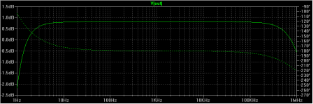
Some data from my latest project, an OTL - OCL headphone amp, with bias servo, 6N6P WCF output stage.
It manages to push out 60mA, which is 60mW into 32 ohm cans, at 0.2% THD. Zout is ~1.7 ohm over the entire audio range. Have a look at attached diagram for (simulated) frequency response and phase shift.
Why would anyone want an output xfrmr for tube headphone amps?
Attachments
Some data from my latest project, an OTL - OCL headphone amp, with bias servo, 6N6P WCF output stage.
It manages to push out 60mA, which is 60mW into 32 ohm cans, at 0.2% THD. Zout is ~1.7 ohm over the entire audio range. Have a look at attached diagram for (simulated) frequency response and phase shift.
Why would anyone want an output xfrmr for tube headphone amps?
Any chance of you posting the schematic?
Cheers
Ian
Any chance of you posting the schematic?
It's not finished yet. Still needs an input buffer to shift the signal down to the negative rail. Also, a startup protection may be required, depending on how the tubes and servo power up. So, it's just the basig engine for now. Note, although this shows 32 ohm load, the circuit works stable for 600 ohms as well, your just need to reduce the nfb.
Scheme and response at 2Hz & 500kHz attached. Try that with a transformer
PS: I just figured the TL431 may need to be bypassed to cope with the very high frequencies..
Attachments
Last edited:
Scheme and response at 2Hz & 500kHz attached. Try that with a transformer
sure, but what's the point ? You can have pretty much a flat response from 20hz to 20khz with a decent transformer (can be quite cheap if you go parafeed) and that's all that matters.
And honnestly, I would never dare to use a headphones amplifier with +/-150V supplies without a cap or transformer at the output. Way too many things can go wrong. An output cap makes things easier, safer without sonic disadvantages if properly sized.
Last edited:
sure, but what's the point ? You can have pretty much a flat response from 20hz to 20khz with a decent transformer (can be quite cheap if you go parafeed) and that's all that matters.
Flat response is not all that matters. There's also phase shift and distortions, which rise at the extremes of the audio range when going thru an opt.
And while the sonic impact of phase shifts may be debateable, the limits on nfb are not.
And honnestly, I would never dare to use a headphones amplifier with +/-150V supplies without a cap or transformer at the output. Way too many things can go wrong. An output cap makes things easier, safer without sonic disadvantages if properly sized.
You are right. I delved in a little further and it's too dangerous, at least without elaborate protection. Just about every failure on the output tube - which will happen sooner or later - will kill the phones, and probably hurt some more. An output cap is safer, just make sure you use high quality stuff. The usual 'lytics will probably also short out, sooner or later, resulting in the same hazards (if your output is not dc free for other reasons).
Also, with OCL you don't gain as much as you would think, since you only move the big ole cap to the nfb network.
In the end, it's probably worth it to use both the dc servo and an output cap. This way, no single failure will kill your phones, while the numbe of caps in the audio path remains the same.
Fair enough wrt phase shifts and thd (mostly at the lower frequencies).Flat response is not all that matters. There's also phase shift and distortions, which rise at the extremes of the audio range when going thru an opt.
And while the sonic impact of phase shifts may be debateable, the limits on nfb are not.
Limits on nfb are indeed clear. I must admit that my latest builds didn't use any, so that was not of concern to me. An advantage of headphones is that power requirements are so low that you can achieve low thd even without gnfb.
Agreed on safety.
I found this site who are offering pcb's for a muting and protection circuit. This is the schematic:

It would go along with a OCL design. Any opinions on performance and safety?
I also had another look at the OTL design and came up with the attached schematic, this time using output caps. Frequency response is a little narrower, I needed to cut the top and bottom end a little to keep the feedback loop stable and to avoid overshoots and ringing. Zout is <0.2 Ohms and THD <0.03 at full power into 32 Ohm load, thanks to large nfb >50 dB.
If my thinking is still healthy, the nfb loop should also correct for any possible distortions originating from the output cap as well as the bypass cap?
Attachments
It would go along with a OCL design. Any opinions on performance and safety?
This kit is using relays which are not rated for high voltage. It works well (I've used and tested derivations of it for solid state amps) but you'll need to adapt it. You might need to lengthen the startup delay too. Sorry if I'm stating the obvious.
As for the latest amp, it seems sound. Of course, the difficulty will be to build it in such a way that it is stable. With that much feedback, do you really need the lt1086 ? How much a difference in sims do you get with either a diodes string or simply a resistor instead ?
This kit is using relays which are not rated for high voltage. It works well (I've used and tested derivations of it for solid state amps) but you'll need to adapt it. You might need to lengthen the startup delay too. Sorry if I'm stating the obvious.
The obvious is, well, pretty obvious.
About the startup delay, wouldn't the protection circuit kick in right from power up and leave the relay open as long as there's a voltage offset? And only close the relay once the dc conditions have stabilized and fallen below the trigger threshold?
As for the latest amp, it seems sound. Of course, the difficulty will be to build it in such a way that it is stable. With that much feedback, do you really need the lt1086 ? How much a difference in sims do you get with either a diodes string or simply a resistor instead ?
The snubber at the input should suppress all oscillations above the audio range. The following stages are very wideband and phase shifts in the audio range between input and output are minimal.
Of course you can simply use a 150R resistor in place of the LT1086. The LT1086 simply forces the optimum current thru the output triodes at all times, regardless of tube variations and ageing.
- Status
- This old topic is closed. If you want to reopen this topic, contact a moderator using the "Report Post" button.
- Home
- Amplifiers
- Tubes / Valves
- Tube headphone amp