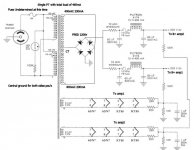
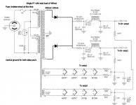
I was considering using one central PT in this power supply schematic from a 400-0-400 Hammond PT with double the asked-for per-channel current requirements.
Each side asks for 230mA, I intend on using one single 400-0-400 Hammond tranny with 465mA total load.
Would it be possible to keep all components post-tranny in this design the same and just make a central tap for both sides power draw?
The original PSU schematic: http://www.plitron.com/images/Diagrams/vtvkt882a.gif
I have removed the -80v power supply for now so as to simplify the nitty-gritty, I intend on making the -80v supply with a seperate PT later on as all the Hammond transformers have 50v only. not 70v.
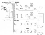
Attachments


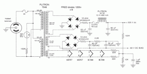
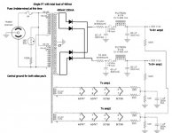
Unless I removed the filter caps from ground and placed them on neutral of the rectified side of each channels PSU circuitry.
However I am puzzled as to what will happen with the filament supplys and their associated unmodified 220r and caps, what effect will those see.
Like this:
However I am puzzled as to what will happen with the filament supplys and their associated unmodified 220r and caps, what effect will those see.
Like this:
Attachments
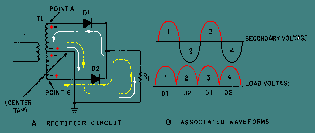
Oops you're right... too early in the morningNo that won't work, now if I done that then both neutral of the rectified side and neutral of AC side would be the same!, Ie complete meltdown.

Why use a bridge rec at all? Why not just 2 diodes, as the transformer was designed for?

That looks OK. You can lose the 10 ohm resistors- the input cap is reasonably sized, and they'll only waste power and increase ripple. The fusing on the secondary side may or may not be problematic.
Describe a spiral staircase without using your hands.
Sorry for all of the image postings but I can't explain it well in text ;\
Describe a spiral staircase without using your hands.
Now everything told me that this schemat does not work, and I was right, it does not work..
I ran a 12v center tapped testbed for this design.
Giving a reading using the center tap as neutral and one of the taps as active on my DMM I was to naturally conclude that it was AC, my DMM correctly displayed 12volts AC and 0v DC.
Now when I placed the diodes into position I got 12volts DC reading off of two of the diodes at which were connected together and 24volts AC out of the diodes!!
Is this normal!?
The transformer is normally rated as 12-0-12...
Ahh yes the AC hum, it must be DC because it manages to drive a 12volt load perfectly fine without any overload, infact the transformer is so weak in current that the fan brings down the voltage to 10v and the fan sounds like it is running at 10volt instead of the normal high-squeal 12volts...
So I am therefore concluding that the DMM is merely reading the AC ripple and translating it as if it was true AC, However I am going to check up on this by placing a large 40v capacitor in-line and reading it with an Oscilloscope.
So I am therefore concluding that the DMM is merely reading the AC ripple and translating it as if it was true AC, However I am going to check up on this by placing a large 40v capacitor in-line and reading it with an Oscilloscope.
- Status
- This old topic is closed. If you want to reopen this topic, contact a moderator using the "Report Post" button.
- Home
- Amplifiers
- Tubes / Valves
- Hammond PT and KT88 Design costs.