Hi guys
I've tinkered with a fair number of SS amplifiers and thought I might try my hand at a valve operated power amplifier for a change. I'm looking for simple topologies to begin with and really just need a steer in the right direction rather than a kit recommendation or circuit to copy. I've read JLH's book on valve and transistor amplifiers.
EDIT: probably worth mentioning that I have some large floor standing speakers around 91dB that by my measurements and calculations should sing with 10W, and it would be nice if the amp could ran these. On the other hand I have all the parts to build some HE Econowave loudspeakers that a "fleapower" valve amp would do justice to - to date I've simply lacked the motivation to build the cabs and assemble them.
Last edited:
Just as important as speaker sensitivity is the impedance curve. Tube amps don't have gargantuan damping factors and do best with speakers whose impedance curve is reasonably flat. Look here where the need to derate speakers, due to impedance curve dips, is discussed.
BTW, Paul Joppa has provided us with a useful rule of thumb in the mating of amps and speakers. Joppa's Rule states that an amp/speaker combo should be capable of producing 102 dB. SPL peaks at a 1 M. distance, in an "average" sized listening space. Honest 91 dB. sensitive speakers require upwards of 15 WPC.
I say NO to the 300B SET idea, as the O/P transformers needed are horribly expensive. For a 1st build, a PP setup will cost less and (IMO) have a greater chance of success.
Member
Joined 2009
Paid Member
Since you are looking to learn and play, going for the ultimate amplifier isn't the place to start perhaps (you'll finish the journey too soon !!!).
I started with a simple SET amp. It turned out well even though it isn't highly regarded, and it has seen more use than any other amplifier I've built or owned...
http://www.diyaudio.com/forums/tubes-valves/167872-my-cellini-triode-amp.html
I started with a simple SET amp. It turned out well even though it isn't highly regarded, and it has seen more use than any other amplifier I've built or owned...
http://www.diyaudio.com/forums/tubes-valves/167872-my-cellini-triode-amp.html
Using Pauls rule of thumb (see Eli's post above).
1 Watt => 91dB
2 Watts => 94 dB (+3dB power increase is double the power)
4 Watts => 97 dB
8 Watts => 100 dB
16 Watts => 103 dB
So 10 Watts will probably do but 15 Watts would perhaps be better (to achieve that 102dB).
300B SET will give you 7 to 8 Watts - probably not enough and expensive although if you decide to go that way give me a PM (I have power and output trannies and 300B's for such a project on my shelf in Adelaide, but never got around to it).
Pentode Mode Push Pull 6V6 or EL84 will give 14W and 18 W respectively but require a lot of feedback.
Ultralinear Mode 6V6 or EL84 will give about 10 Watts which may be enough.
Best might be Push Pull Class A Triode Mode EL34 for about 16 watts
Eli's "El Cheapo" circuit could easily be adapted to accommodate Triode Mode EL34.
For Pentode mode EL84 look for SY's "Red Light District"
For Ultralinear mode EL84 or 6V6 look for my "Baby Huey" or Morgan Jone's "Bevios Valley".
If you eventually build the speakers for a flea power amp then there are a lot more options, even a 6EM7 "spud" (single tuber) amp might be enough.
Cheers,
Ian
Ian,
I have my doubts about the "El Cheapo" small signal circuitry having enough "sock" to drive both EL34s and the NFB loop. OTOH, 7591 "finals" will be fine. I call such an arrangement "El Cheapo Grande". The amp could be built with triode/UL mode switches, to provide either finesse or power. 30 honest WPC should be easy enough from UL mode PP 7591s.
For several reasons, I highly prefer combination bias for 7591s. "Stand" each O/P tube pair on a 100 Ω/470 μF. network. The bulk of the bias voltage comes from a C- supply. Notice the very convenient test point. Also, only 1 trim pot./channel is needed.
Thanks Eli for correcting my "blue" (Oz vernacular for stuff up).
Can you post a schematic link?
Ranchu32
I have limited experience with 5791 (only with an Ampeg Guitar Amp) but I did not like the JJ 5791. When I tested them on an AVO MK3 Tube Tester they were not much like a "real" 5791 (in this case the "real" 5791 I compared against were some old RCAs). I note Evatco in Brisbane have ElectroHarmonix 5791. If you go the "El Cheapo Grande" route I would suggest you try those.
Cheers,
Ian
Hi, Welcome to the world of tubes. I agree that a push pull circuit would be better to start with considering your speakers. I would suggest a mildly driven pair of EL34s or even KT77s. Even in class A U/L push pull you can get a very clean 12-15 watts. Use Edcor CXPP25-MS-XX iron. Inexpensive and quite good for such applications. In class A U/L I would use the XX=8K ones. A lower impedance for AB class.
Thanks Eli for correcting my "blue" (Oz vernacular for stuff up).
Can you post a schematic link?
Ranchu32
I have limited experience with 5791 (only with an Ampeg Guitar Amp) but I did not like the JJ 5791. When I tested them on an AVO MK3 Tube Tester they were not much like a "real" 5791 (in this case the "real" 5791 I compared against were some old RCAs). I note Evatco in Brisbane have ElectroHarmonix 5791. If you go the "El Cheapo Grande" route I would suggest you try those.
Cheers,
Ian
Ian,
I've never put a schematic for the "Grande" together. Go by the original "12" W. tube schematic, to get a "feel". The taller B+ rail needed by 7591s allows 12AT7/ECC81 plate loads to increase to approx. 80 Kohms. Use a carbon film part in series with a 50 Kohm wire wound part, to avoid excessive "peaking". Use 330 Kohm grid to ground resistors on the 7591s. Increase the interstage coupling cap. value, proportionately.
As you are comparatively close to the OP, sending him to appropriate places for "iron" is in your hands. Shipping heavy magnetics over long distances is expensive. Also, import duties have be taken into account. IMO, buying from the U.S. is probably a bad idea.
Definitely use EH 7591s, as all of JJ's Octal production is highly suspect.

I call every everybody's attention to the UL mode operating conditions shown on the 7591 data sheet previously linked. The direction to go in is pretty well outlined.
Attachments
Thank you all for some very useful information and opinions!
I've shied away from SS Class A to date for the simple reason that big heat generating amplifiers aren't really suited to sunny sub-tropical Brisbane for most of the year. SE is horribly inefficient (even more so than PP Class A) and even though I have no doubt that nicer examples sound wonderful, I can't imagine it being practical for my climate unless the output power is impractically low (<5W).
So I suspect that I'm interested in going down a PP Class AB route to begin with, so that I can get some gratifying results with the floorstanders that I know and love. I suppose I would be persuaded otherwise if the extra build cost proved prohibitive, the complexity is significantly greater, or the sound quality were severely compromised.
In my "googling" I stumbled across this Australian web page with some good reports on locally available output transformers that might prove viable for a low-medium power PP output stage. Any thoughts?
Cheap Output Transformers
EDIT: Does anybody know of any local sources for suitable step-up transformers that can generate the HT rails? Safety concerns at these voltages duly noted, not only handling and testing precautions, but also observance of creepage distances and insulation. 600-1000V is not something to be taken lightly!
Last edited:
No!!!!! Line trannies are ok for a bit of fun, but if you are heading into AB1 and putting some effort in, make a line in the sand and commit to decent iron.
There is an EXCELLENT thread here on the design and build of an AB1 amp that is pretty much ion the money for your needs. Its long, but worth the evening reading through as it will answer every question worth asking on the subject.
There is an EXCELLENT thread here on the design and build of an AB1 amp that is pretty much ion the money for your needs. Its long, but worth the evening reading through as it will answer every question worth asking on the subject.
Last edited:
OK, so I've been reading the Valve Wizard, Rod Elliott and chrish's thread while I wait for my copy of Morgan Jones' book to arrive from Amazon. There is a lot of information to process, but a few ideas are solidifying in my mind:
- A push-pull output stage, biased into Class A or Class AB1 for 10-15W+ output power.
- The output transformer (the iron?) seems to be the limiting factor in any valve amplifier so it makes sense to spend money here, particularly if pushing the stage into AB1 or AB2.
- I should be able to source an isolation transformer (240VAC in/out) relatively easily, giving approx. 300V of well regulated DC on the HT rail. I have an idea for a solid-state ripple eater that I'll draw in Eagle and post here when I get a chance. I suppose the HT voltage will have a bearing on choice of output valves and power ratings.
- I like the idea of triodes for best linearity but some commentators lament the difficulties of driving these valves with an "incredibly low input impedance as low at 47k". I know that I could easily build a solid-state driver stage with many 0's THD capable of driving that impedance without breaking a sweat. Is there any merit in building a hybrid of sorts, with a solid state driver stage and power valves / output transformer? The output stage could be left outside the feedback loop so that the valve harmonics come through.
If you like triodes, you should be aware that "Schaded" feedback pentodes give better triode curves than the best triodes. And there is a long thread here on Pete Millett's DCPP amplifier which uses Schaded pentodes for output, and is easy to build.
George (Tubelab) has then taken it to multi-hundred Watt heights in the thread using cheap TV tubes.
http://www.diyaudio.com/forums/tubes-valves/151206-posted-new-p-p-power-amp-design.html
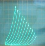
1) Here is a Schaded ($5) 6HJ5 curve set (50 mA/div, 50V/div), the amp can do 100 Watts output, leisurely, with a pair of these:
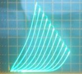
2) and a Schaded 21HB5A ($1 each, when on sale), good for 60 Watts out:
3) Schaded 12GE5/6JN6, 6JN6 is the original tube used with the DCPP, good for 20 Watts with original spec'd 8K primary, 50 Watts with a 4K primary
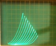
4) and a 300B triode curve set for comparison
note: above tube pinouts (except 6JN6) are different from the PCB offered for the DCPP Amp
George (Tubelab) has then taken it to multi-hundred Watt heights in the thread using cheap TV tubes.
http://www.diyaudio.com/forums/tubes-valves/151206-posted-new-p-p-power-amp-design.html
1) Here is a Schaded ($5) 6HJ5 curve set (50 mA/div, 50V/div), the amp can do 100 Watts output, leisurely, with a pair of these:
2) and a Schaded 21HB5A ($1 each, when on sale), good for 60 Watts out:
3) Schaded 12GE5/6JN6, 6JN6 is the original tube used with the DCPP, good for 20 Watts with original spec'd 8K primary, 50 Watts with a 4K primary
4) and a 300B triode curve set for comparison
note: above tube pinouts (except 6JN6) are different from the PCB offered for the DCPP Amp
Attachments
Last edited:
- I like the idea of triodes for best linearity but some commentators lament the difficulties of driving these valves with an "incredibly low input impedance as low at 47k". I know that I could easily build a solid-state driver stage with many 0's THD capable of driving that impedance without breaking a sweat. Is there any merit in building a hybrid of sorts, with a solid state driver stage and power valves / output transformer? The output stage could be left outside the feedback loop so that the valve harmonics come through.
http://www.geofex.com/Article_Folders/mosfet_folly/mosfetfolly.htm
Also take a look at Tubelab's PowerDrive and at Pete Millett's Class A2 driver board. Pete's is available ex fleaBay, not sure if Geoge (Tubelab) has PowerDrive boards or not, but hte circuit is nothing difficult to scratch build.
- Status
- This old topic is closed. If you want to reopen this topic, contact a moderator using the "Report Post" button.
- Home
- Amplifiers
- Tubes / Valves
- New to valve amplifiers