Hi all,
Recently built a tube phono preamp.
It sounds quite nice, but could be less noisy, so I will try CCS instead of anode resistor.
But how (if at all) will this affect my RIAA component values?
(I have been using the well known RIAA calculator to find the original values)
Harm
Recently built a tube phono preamp.
It sounds quite nice, but could be less noisy, so I will try CCS instead of anode resistor.
But how (if at all) will this affect my RIAA component values?
(I have been using the well known RIAA calculator to find the original values)
Harm
Attachments
Hi, A related question....how did you determine that the resistor needed to be smaller. I can see that if the CCS effectively increases the output impedance of the circuit but I was not aware that the CCS would do this. In all the designs I have seen using passive RIAA compensation the resistor plus the effective output impedance of the preceding stage are added together to get the right response.
Recently built a tube phono preamp.
It sounds quite nice, but could be less noisy
What kind of noise? A CCS is very unlikely to provide much improvement and may even increase noise. What size is the input grid stopper? The unbypassecd cathode resistors are also not helping.
In the original circuit the impedance at the anode of the first stage is anode impedance in parallel with the anode resistor. In the modified circuit it is just anode impedance, so will be greater. Hence the build-out resistor needs to be smaller in order to present the same impedance to the rest of the RIAA network. Given this, the rest of the network needs no change. Note that 'anode impedance' is modified by the unbypassed cathode resistors, so will be greater than the datasheet value.
I agree with Merlin. Why do you think a CCS will improve "noise"?
I agree with Merlin. Why do you think a CCS will improve "noise"?
What I learned from reading several forums on the internet is that the use of active loads (CCS’s) in vacuum tube amplifiers has several advantages over resistive loads. These including full mu of the tube, lower distortion, and greatly improved power supply noise rejection.
I've never experimented with this philosophy, but would like to give it a try.
The tubes that I'm using are 5751 in the first, and 12AX7 in the second stage (2nd stage not on the attached schematic)
To increase gain is not my primary goal, (less gain would even be better), but
to reduce hum is what I'm looking for
Ah, you mean hum rather than (random) noise. Are you using DC heaters?To increase gain is not my primary goal, (less gain would even be better), but
to reduce hum is what I'm looking for
To answer you original question, the original source resistance of the input stage is about 45k ohms. With a CCS it will be about 78k ohms, so you would need to reduce the 219k resistor by 78-45=33k ohms (i.e. you need 186k)
Last edited:
Yes, I meant hum rather than noise and yes, I 'm using DC heaters, based on LM317 voltage regulator. Each channel independently supplied and lifted up to appr. 80V to keep voltages within tube limitations.
Initially I used 12AX7 in the first stage too. Less hum, but too much gain. With 5751 sufficient gain, but too much hum. Hence the CCS option.
Initially I used 12AX7 in the first stage too. Less hum, but too much gain. With 5751 sufficient gain, but too much hum. Hence the CCS option.
Welcome in the club of hum-fightersYes, I meant hum rather than noise and yes, I 'm using DC heaters, based on LM317 voltage regulator. Each channel independently supplied and lifted up to appr. 80V to keep voltages within tube limitations.
Initially I used 12AX7 in the first stage too. Less hum, but too much gain. With 5751 sufficient gain, but too much hum. Hence the CCS option.

Please can we put an extra rule in forum rules: when you have hum please call it 'hum', when you have noise please call it 'noise', and when you have oscillation please call it 'oscillation'. Too many threads spend the first two pages chasing the wrong symptom.
To reduce hum you need to find its source. Poor grounding is a likely candidate. People often say something like "I used a star, so it can't be grounding at fault". Then we find that they have injected hum right into the ground point!
To reduce hum you need to find its source. Poor grounding is a likely candidate. People often say something like "I used a star, so it can't be grounding at fault". Then we find that they have injected hum right into the ground point!
This is exactly my question Bruce. If 219K series resistor needs to be smaller, then this will inluence the 33K2 and capacitor values as well. Or am I wrong?
Harm
R1/R2 = ((T3-T4)*(T4-T5))/(T4^2)
or about 6.877
Just to avoid any confusion, changing the build-out resistor when changing the anode load is done to avoid the need to change any other component. This assumes, of course, that the net anode impedance was taken into account when calculating the resistor value. Note that for RIAA networks, like all such networks, it is the net impedances which matter not the component values. The components will find themselves in series or in parallel with other circuit impedances so it is the net value which counts.
So no, once you change one component value to compensate for a change in circuit impedance nothing else has to change.
So no, once you change one component value to compensate for a change in circuit impedance nothing else has to change.
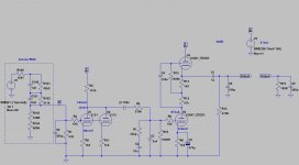
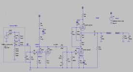
Here is the complete schematic, including the CCS adaption.
If recalculation results in changing the the 219K resistor to 190K, then will this affect the other RIAA network values, was the original question.
Thank you all for your comments.
(still not quite happy with overall performance)
Harm
If recalculation results in changing the the 219K resistor to 190K, then will this affect the other RIAA network values, was the original question.
Thank you all for your comments.
(still not quite happy with overall performance)
Harm
Attachments
Here is the complete schematic
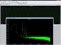
If you don't use any filtration (schematic 1) between PSU, AND each stage, you likely built a good mixer!
")
See my simulated FFT: only 10mV (100Hz) hum over +300V generates enormous HUMM on the output.
If you use correct R-C filtrations, this hum will decrease 50-60dB!
Good CCS (for example cascode depletion MOSFETs - LND150-) also helps a lot, but if the second stage B+ is not filtrated it's worthless.
p.s Are you sure, that RIAA (R, C) values are all correct for parallel 5751s? Simulated curve is very ugly.
Attachments
- Status
- This old topic is closed. If you want to reopen this topic, contact a moderator using the "Report Post" button.
- Home
- Amplifiers
- Tubes / Valves
- RIAA network adjustment