Do you have a schema of it?It would be interresting.Another possibility is the 6N1P. John Tucker used this combination for is amps. The 6N1P had a combined shunt voltage regulator and CCS plate load - the second half of the 6N1P was used for the shunt voltage regulator.
Retsel
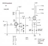
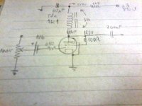
The operating points are on the schematic: Ep = 144V; Eg = -1V; Ip = 10mA; gain = 46
Were the Ep and Ip same for 6N23P also? If not, what were they?
Not as designed, if you remove the electrolytic you can use a string of vr tubes, (or a single vr tube) however note that they will be much noisier than a bypassed string of zeners, and you can't bypass them with anything more than about 0.047uF before you run the risk of creating a relaxation oscillator. I suspect you are better off with the zeners on several counts.
Not as designed, if you remove the electrolytic you can use a string of vr tubes, (or a single vr tube) however note that they will be much noisier than a bypassed string of zeners, and you can't bypass them with anything more than about 0.047uF before you run the risk of creating a relaxation oscillator. I suspect you are better off with the zeners on several counts.
Apart from removing the electrolytic, is there anything else I should consider? I might try it both ways. The schematic looks fun.
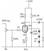
In diag 2 you are shunting approx 7.4mA through the zener string + g2. You will need a lot more current fot the vr tube. From memory, around 20mA should suffice, plus say 2.5mA for g2 , making 22.5mA total. Therefore the shunt resistor should be around 8k9 Let's take the standard value 8k2 for a combined current flow of 24.4mA.
A neat trick is wire the bottem leg of the vr tube to top of the cathode resistor instead of ground, reducing its value and increasing gain. In this case the current flowing through it would be approx 20mA plate current plus 24.4mA vr tube plus g2 = 44.4mA total. For a cathode voltage of 1.4V a replacement cathode resistor of approx 32R would be required.
A neat trick is wire the bottem leg of the vr tube to top of the cathode resistor instead of ground, reducing its value and increasing gain. In this case the current flowing through it would be approx 20mA plate current plus 24.4mA vr tube plus g2 = 44.4mA total. For a cathode voltage of 1.4V a replacement cathode resistor of approx 32R would be required.
In diag 2 you are shunting approx 7.4mA through the zener string + g2. You will need a lot more current fot the vr tube. From memory, around 20mA should suffice, plus say 2.5mA for g2 , making 22.5mA total. Therefore the shunt resistor should be around 8k9 Let's take the standard value 8k2 for a combined current flow of 24.4mA.
A neat trick is wire the bottem leg of the vr tube to top of the cathode resistor instead of ground, reducing its value and increasing gain. In this case the current flowing through it would be approx 20mA plate current plus 24.4mA vr tube plus g2 = 44.4mA total. For a cathode voltage of 1.4V a replacement cathode resistor of approx 32R would be required.
Could I take that further and replace the resistor with a LED of suitable voltage? I realize it might be a problem if I do this with the vr tube connected above the led.
The HLMP6000 which I use for LED biasing will give a cathode voltage of 1.6V with a maximum continuous current capacity of 50mA. Running 44mA through it may be too close to Imax for comfort, in which case connecting the lower leg of the vr tube to earth may be more prudent.
Moreover, when using LED biasing there would probably be no real benefit conferred by connecting the vr tube to cathode.
Moreover, when using LED biasing there would probably be no real benefit conferred by connecting the vr tube to cathode.
Last edited:
Yes, this is my experience: I needed to use an 680R resistor in series with g1 AND a long ferrite bead in series with anode, when using E810F (not E180F - great tube but not so like E810F), to stop VIOLENT VHF oscillationsHello,
Check D3A, E180F (cheap), E810F, E280F, EL802, C3M, 6S45P
Keep in mind those are high gm tubes and will need oscillation prevention measures, such as grid resistors.
 . I used the E810F to drive my 300B amp with an anode choke and old Siemens telecom 200nF/500V Styroflex capacitor.
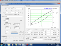
I have an Ronald Dekker's µTracer and I measured the SQ Philips E810F transconductance: more than 60mA/V at 50mA/125V
but of course I use with far less current (1,5V bias from battery and 125V on anode; I need to measure to check the resulting transconductance in that bias point).When VHF oscillations stoped (and noise drop to an scary low level), the sound was very good, becoming my favorite 300B driver, recommended
...Yes, this is my experience: I needed to use an 680R resistor in series with g1 AND a long ferrite bead in series with anode, when using E810F (not E180F - great tube but not so like E810F), to stop VIOLENT VHF oscillations
I have an Ronald Dekker's µTracer and I measured the SQ Philips E810F transconductance: more than 60mA/V at 50mA/125V
When VHF oscillations stoped (and noise drop to an scary low level), the sound was very good, becoming my favorite 300B driver, recommended
Thank you for the suggestion. If you have a schematic I'd love to see it!
I agree from experience with D3a, E180F and E280F as triode connected pentodes, with grids tied to anode (and not to kathode), Also with the need for essentially RF layout, CC stoppers on grids and anode, also with ferrite on G1 and also heater pins. Tough tube to tame, but if you can stop it from wanting to oscillate, then very hard to beat, especially for mu and low Rp.
E180F is a bargain, as mentioned before, and… I also prefer E280F from D3a for common cathode amp, for grounded grid and kathode drive for low Zin for certain D/A chips (TDA) its a bit different, but still better than most IMHO.
L.H
E180F is a bargain, as mentioned before, and… I also prefer E280F from D3a for common cathode amp, for grounded grid and kathode drive for low Zin for certain D/A chips (TDA) its a bit different, but still better than most IMHO.
L.H
I built it "on the fly", so I need to draw the schematicThank you for the suggestion. If you have a schematic I'd love to see it!
.Soon I have the time to make the schema and post here.
I will measure all working voltages.I would change the resistor + cap from the cathode to 2 Battery NiMH 2.6v
All e280f e180f D3a work very good my choice is e180f, gentle as 6sn7 low Ri, and to my ears very good timbre
http://www.diyaudio.com/forums/tubes-valves/102335-ixys-ixcp10m45s-ic-5.html#post1221531
All e280f e180f D3a work very good my choice is e180f, gentle as 6sn7 low Ri, and to my ears very good timbre
http://www.diyaudio.com/forums/tubes-valves/102335-ixys-ixcp10m45s-ic-5.html#post1221531
Here's my SE 2A3 amp using the E180F. One nice point about the E180F, besides the fact that it is excellent sounding, is that it is cheap to buy. I bought a dozen and got several pairs that matched for plate current at the operating point. Note the choke is by Electra-Print and the voltage on the cathode of the E180F is just over 1V. I had previously used a 6N23P-EV in the same amp although with LED bias. Replacing the 6N23P was a major step forward in reducing "glare" and increasing transparency.
got few ef80, wondering if can be used here
I take an foto from my hand drawing notes (schematics) for not awaiting eternally to make an KICAD draw schema... NF is the ferrite bead. The battery furnishes 1,6V bias and the 3k9 supply dropper is for both channels.
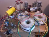
And one photo from my ugly abused prototype
My µTracer measurements from E810F oscillated this time (need more stoppers ...), but even so I published here to show the outrageous high transconductance for a 300mA/6V3 heater tube! (ex.: 17mA/V with 7mA!)
I know several JFETs witch don't have such gm at that current levels.
I have some E180F, E280F, 6CL6, 12BY7A, EF184, 6FQ7 and some others types. If someone has interest in some bias/curves measurements from these, I'll be happy to measure (and if tube oscillates, I tame the oscillations and I advise to caution against oscillations).
NF is the ferrite bead. The battery furnishes 1,6V bias and the 3k9 supply dropper is for both channels.And one photo from my ugly abused prototype
My µTracer measurements from E810F oscillated this time (need more stoppers
...), but even so I published here to show the outrageous high transconductance for a 300mA/6V3 heater tube! (ex.: 17mA/V with 7mA!)I know several JFETs witch don't have such gm at that current levels.
I have some E180F, E280F, 6CL6, 12BY7A, EF184, 6FQ7 and some others types. If someone has interest in some bias/curves measurements from these, I'll be happy to measure (and if tube oscillates, I tame the oscillations and I advise to caution against oscillations).
Attachments
Last edited:
Low capacitance MOS
. More tubes in the candidate list!
And these types will help uses with high rp tubes, thanks the low capacitancei am surprised nobody uses sic fets
low ciss, low id types exist. all rated 1200v
should be better than 2nf si fets, and faster
. More tubes in the candidate list!- Home
- Amplifiers
- Tubes / Valves
- 300b with single stage driver, C3M or?