finally in this splurge:
https://grabcad.com/library/kt88-amplifier-1
for all shiny 3d models and so on.
please like if you do it makes my inbox all funky")
https://grabcad.com/library/kt88-amplifier-1
for all shiny 3d models and so on.
please like if you do it makes my inbox all funky
update
Hi Soulmerchant, didn't try the Sowter due to the way I cunningly hid the connections for the transformers under the switching board..
I'd agree though, someone *admitted* to making them and I am quite pleased - they were not expensive. Sure I'd be disappointed in comparison though. The Sowters are SE08A, much larger and heavier - do need to do testing on the amp though to find response etc. I have new Sovtek tubes on their way so there is a round of optimisation to get through.
More generally I have a few numbers for now though! KT88's are biasing at -30v with a 325ohm cathode resistor so that's 80mA, which seems right according to the datasheets but I think I'd like to shove the operating point left. Need to dig out the dummy loads before getting any further.
preliminary prods with a scope show a nice sine wave at 1khz but, frankly, without those dummy loads it was all getting a bit loud and unpleasant.
Cheers
Andy
Hi Soulmerchant, didn't try the Sowter due to the way I cunningly hid the connections for the transformers under the switching board.
. I'd agree though, someone *admitted* to making them and I am quite pleased - they were not expensive. Sure I'd be disappointed in comparison though. The Sowters are SE08A, much larger and heavier - do need to do testing on the amp though to find response etc. I have new Sovtek tubes on their way so there is a round of optimisation to get through.
More generally I have a few numbers for now though! KT88's are biasing at -30v with a 325ohm cathode resistor so that's 80mA, which seems right according to the datasheets but I think I'd like to shove the operating point left. Need to dig out the dummy loads before getting any further.
preliminary prods with a scope show a nice sine wave at 1khz but, frankly, without those dummy loads it was all getting a bit loud and unpleasant.
Cheers
Andy
Attachments
ok so to keep posting:
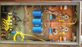
One schematic with voltages. according to SEampCAD I'm not going to do much better with the O/P stage :-/ So here she is at present.
TO-DO
Change the OP caps! as there is a point in between the 6 and the 3
Reduce voltage to input stage with further RC filter say 300 V
Move op point for 6J5G to -4v rather than -6V
Add feedback from transformer OP to 6j5 cathode.
Notes:
At max volume there is a faint - faint hum with ear to speaker (Castle Harlech 2) deemed acceptable as I get far worse from commercially available amps. So that's NICE, passive supply works.
Those heading to Grabcad will find a 30sec delay timer as part of the switching board, not implemented but meant for switching of an SSR for HT
Attachments
Hi Andrew, did you ever consider trying LED bias on the input tube? You might try a few green and a red in series to get something close to your preferred bias point. Bass response will be very firm after you try it...
Its not hard to do. If you want to try it, make a little rig with a 9V battery, and low ohm resistor in series with the LED, then match LED's forward drop voltages so you bias at exactly the same voltage channel to channel.
Just a thought. I have done it before. I always liked KT88 much more in triode mode.
Ian
Soulmerchant
No never tried it - question is how does that fare against the current source? Not an expert and this rather confuses my little brain but I'm having difficulty vs a current source and a given voltage drop
I did mention I'm a mechanical engineer right?? :-D
A few LED's in series on the cathode instead of your 820 ohm resistor. That's what I mean.
LED's hold a very steady forward voltage, regardless of current flow. A resistor will take time to recover, which is why many by-pass them with a capacitor. As I think you noted, another solution to this is the application of a tiny amount of global feedback.
The LED solution is very cheap and easy. If you have a chance, give it a try - I am certain you will not regret it!
Ian
Last edited:
Member
Joined 2009
Paid Member
So initial FAIL on feedback!
soulmerchant - I will try the LED trick instead or as well as. I didn't make any measurements with FB as its a school-night, but the character of the amp went south. Of course it was a quick hack and there is the possibility of driver error but "ugh". I quickly put it back to how it was.
As I'm typing this I'm wondering If LED bias will negate any GFB assuming its fed into the cathode. Much to try and as I intend to use this driver circuit, or a variation of it again it's all good.
Bigun - I also have that about LED's in the back of my mind, but I think 7-8 MA is in the OK area? Still it's easy to try 3 or 4 led's in a row.
Andy
I read somewhere that LEDs need decent current flow to avoid high dynamic resistance.
True. I thought 7mA would be enough, but it depends on the LED specs. The cheapest ones are often best.
I have done cheap red LED's and green LED's at this level of current in series with great results many times.
OK so LED's installed. Three in a string gave more or less 5.5v drop. First Impressions are MEH not immediately worse or better than the resistor.
led me to another query - Cathode bypass capacitor? Ordinarily I would leave out and take the local feedback. As I've said already, there's plenty of volume so I don't see the need to gain gain. Is that still a valid assumption with little bits of silicon glowing in the tail? I'm not 100% sure, but the volume control doesn't seem so far around...
I should add that I also changed out the 3x 240k resistors in the CCS and replaced with 2 x 180k as the 1/4 watt ones were a little stressed (like going brown stressed)
Andy
as it is
Of course if you're comparing, its as well to use the same output tubes.
Still not convinced but either way it simply isn't worth breaking out the soldering iron again happy (for now)
So this Amp will stay like this I think for now. (Famous last words)
Andy
Of course if you're comparing, its as well to use the same output tubes.
Still not convinced but either way it simply isn't worth breaking out the soldering iron again happy (for now)
So this Amp will stay like this I think for now. (Famous last words)
Andy
Attachments
- Status
- This old topic is closed. If you want to reopen this topic, contact a moderator using the "Report Post" button.
- Home
- Amplifiers
- Tubes / Valves
- KT88 SE