Hello,
I'm restoring a Bogen AP-200 amp and was advised to add a choke to the power supply ( http://www.diyaudio.com/forums/tubes-valves/271088-help-needed-restoring-bogen-ap-200-amp-2.html). I have a few questions about choke addition and think that they might be of interest on its own so started a new thread.
I found the only choke that could be fitted on the Bogen chassis, the Triad Electronics C-36X 0.5 H 300mA 30 Ohms. Bigger chokes such as recommended Hammond 1.5 H will only fit if positioned 5-6 mm from the rectifyer tube and be quickly fried
Will addition of this 0.5H choke do any good in reducing ripples? The amp will be using mostly at low output levels so I'm concerned about the PS hum.
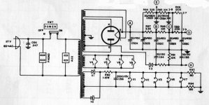
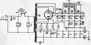
My other question is where a choke should be added. The B+ voltage is taken off the second capacitor, C52B (first picture). I think the choke should be added between the first and second capacitors as shown at the second picture and the B+ should be taken from C52B as before. Is this correct?
I also like to double the capacity of all electrolytes after choke, i.e. C52 B-D, C53 A-C, C54 and C55. Could I do this?
Thanks!
I'm restoring a Bogen AP-200 amp and was advised to add a choke to the power supply ( http://www.diyaudio.com/forums/tubes-valves/271088-help-needed-restoring-bogen-ap-200-amp-2.html). I have a few questions about choke addition and think that they might be of interest on its own so started a new thread.
I found the only choke that could be fitted on the Bogen chassis, the Triad Electronics C-36X 0.5 H 300mA 30 Ohms. Bigger chokes such as recommended Hammond 1.5 H will only fit if positioned 5-6 mm from the rectifyer tube and be quickly fried
Will addition of this 0.5H choke do any good in reducing ripples? The amp will be using mostly at low output levels so I'm concerned about the PS hum.
My other question is where a choke should be added. The B+ voltage is taken off the second capacitor, C52B (first picture). I think the choke should be added between the first and second capacitors as shown at the second picture and the B+ should be taken from C52B as before. Is this correct?
I also like to double the capacity of all electrolytes after choke, i.e. C52 B-D, C53 A-C, C54 and C55. Could I do this?
Thanks!
Attachments
Will addition of this 0.5H choke do any good in reducing ripples?
I think the choke should be added between the first and second capacitors Is this correct?
I also like to double the capacity of all electrolytes after choke, i.e. C52 B-D, C53 A-C, C54 and C55. Could I do this?
Yes, that's the right place, before the output stage "A". You could try a small value power resistor first.
Less hum reduction, but way smaller and easier. Maybe a 10W 10 Ohm wirewound from RadioShack etc.
It will get rather hot, because it burns the charging/discharging ramp waveform on the first cap, as well as the DC bias current drop.
What's the rectifier tube type, because some can't handle more than a 20-30uF cap input filter.
Hold off on replacing the caps with larger ones until you hear the effect of the added choke/resistor.
Last edited:
A 0.⁵H choke will make almost no difference on its own. However, combined with a larger value for C52B it could make some difference.
True… but IF there is "buzz", then even a 0.5 H choke will subdue the buzzy part pretty effectively. The ... (EDIT: not enough current handling, and I didn't read the whole OP post.)
I agree … with the sentiment that a larger C52B would be good. Especially with the larger choke: it has both inductance and series resistance, which decouples it from the rectifier tube, from a peak-current perspective. Bidirectional utility!
GoatGuy
Last edited:
The recitifier is GZ54/5AR4 type, with teh current output up to 250 mA. It can take up to 60 uF cap.
Fitting a bigger choke there is not possible unless it's a heat-resistant one. There are no place underneath the chassis, only on top of it and near the rectifier tube. The big choke such as 1H Hammond 158 T gets too close to the rectifier and it's pretty hot out there.
I like the idea of 10w/10 Ohm wirewound resistor; something like this HLM01010Z10R00JJ Vishay / Dale | Mouser or even this RE65N10R0C02 Vishay / Dale | Mouser although the latter it's non-inductive and so not good here. However, I'm afraid it will toast some components within the chassis.
I like the idea of 10w/10 Ohm wirewound resistor; something like this HLM01010Z10R00JJ Vishay / Dale | Mouser or even this RE65N10R0C02 Vishay / Dale | Mouser although the latter it's non-inductive and so not good here. However, I'm afraid it will toast some components within the chassis.
If you try the resistor, wire it so there is air around all sides, and it doesn't touch anything.
What are benefits of adding these two capacitors?
I suppose a 1uF in parallel to choke forms an LC filter that filters out something... the 120 Hz AC?
And the 0.1 uF in parallel to 52B is a "bypassing" that many solid-state huge capacitors often have "to reduce harshness". Right?
I suppose a 1uF in parallel to choke forms an LC filter that filters out something... the 120 Hz AC?
And the 0.1 uF in parallel to 52B is a "bypassing" that many solid-state huge capacitors often have "to reduce harshness". Right?
IMO, chock 0.5 Hn/30 ohm with parallel 1 uF is better than resistor 30 ohm....
And add 0.1 uF/450V parallel to 52B
Perhaps if you initially get the amp going and tweaked first. Obviously adding a choke is not going to be easy, and is turning out to require compromises.
The addition of a choke was a suggestion as a possible improvement path - the hum may turn out to be negligible - or if it is noticeable then it may not be related to the B+ supply, and so your attention is better spent on getting the rest of the amp settled.
The addition of a choke was a suggestion as a possible improvement path - the hum may turn out to be negligible - or if it is noticeable then it may not be related to the B+ supply, and so your attention is better spent on getting the rest of the amp settled.
1. A 0.5Hy choke will only add smoothing if it is CLC. You can easily use a nice wire-wound resistor for that.
2. a 0.5Hy choke in LC will be noticable, but you will need a different mains transformer since you will lose too many B+ volts otherwise.
so... whoever advised you of this doesn't fully know what they are talking about... stick to the original schematic or re-design the entire B+ power supply. Those are the real choices.
Ian
forget the magnetic choke. Go electronic. Miada regulator or similar. Small, efficient, adjustable, cheap.
if you only want smoothing....
if you only want smoothing....
What else is the discussion about, if not to improve the quality of the DC, by filtering out more ripple? Ji!
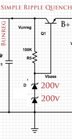
But I do agree with the sentiment … of using a simple active filtering device instead of an inductor. Its amazing what a high voltage "emitter follower" type regulator will accomplish with near-no space, offering great filtering without a zener reference. Or, if you prefer, with a zener reference. Either way, just kind of "gets 'r done".
For … like $3 or less, all in. Go zener (pair of hi-volt types) for the base voltage reference, and now you get a power supply that'll supply an almost invariant B+ within a broad range of power-outlet voltage variation.
Or use a bonafide regulator. "Whatever".
GoatGuy
Attachments
Yeah, filtering ripple.
I decided to go ahead without choke now since its addition might create more problems than it solves (induction for example) and there are a lot of other areas in the amp that need attention.
The idea of active filtering device looks very interesting; what kind of transistor should be used there? Just any with the rated current/voltage, in my case 250mA/450V?
What else is the discussion about, if not to improve the quality of the DC, by filtering out more ripple? Ji!
But I do agree with the sentiment … of using a simple active filtering device instead of an inductor. Its amazing what a high voltage "emitter follower" type regulator will accomplish with near-no space, offering great filtering without a zener reference. Or, if you prefer, with a zener reference. Either way, just kind of "gets 'r done".
For … like $3 or less, all in. Go zener (pair of hi-volt types) for the base voltage reference, and now you get a power supply that'll supply an almost invariant B+ within a broad range of power-outlet voltage variation.
Or use a bonafide regulator. "Whatever".
GoatGuy
Put C52A and C52B in parallel after the rectifier. Then put the choke from that point to where C52B used to be. Add a 220Uf cap after the choke.
The choke will isolate the rectifier from the ripple current of the large cap value, and the combination will filter the ripple effectively.
The choke will isolate the rectifier from the ripple current of the large cap value, and the combination will filter the ripple effectively.
I agree with GoatGuy about the utter convenience of the emitter/source follower type of supply. The regulation can be much improved by supplying the zener from a current source and made absolutely rock-steady by supplying the current source reference from another current source. This probably seems ridiculous but I have such large (and illegal!) mains variation in my area that it has prompted me to experiment.
The idea of active filtering device looks very interesting; what kind of transistor should be used there? Just any with the rated current/voltage, in my case 250mA/450V?
Yep… but choosing beefy is bettah.
ST Part
Is the datasheet for a particularly beefy, inexpensive, high-performance darlington that'd give great regulation. I would probably put a reversed diode across the collector-emitter, so as to provide a shunt-path for all the down-wind (right-hand-side) capacitors when power is turned off … but that's about all.
You do not need a 450 volt part because it will only be dealing with the differential regulation voltage. And that? That would all depend on where you set it with those pair of Zener voltage references.
One could discuss this for many posts. Rest assured: if you wish to optimize for self adjustment (for a variety of power-line voltages, sags, surges), then you'll either not use Zeners (and just use a resistive voltage-divider instead and a capacitor to hold the averaged sub-B+ DC), or, you'll chose Zeners that give the lowest estimated sagged powerline voltage. Like, if you assume 110 VAC instead of 117 VAC or 125 VAC or whatever you generally have at your place.
I've done it both ways. Zener is cheap, good. Just don't choose a base voltage too close to the nominal voltage (you need something to regulate with!), or, too low (being too pessimistic of the municipal power supply).
GoatGuy
- Status
- This old topic is closed. If you want to reopen this topic, contact a moderator using the "Report Post" button.
- Home
- Amplifiers
- Tubes / Valves
- Adding choke to a power supply