I just got a good deal on a lot of 21JZ6 tubes. Spec is attached. I'd like to try triode strapping them. A couple questions come to mind:
- If I connect the beam forming electrodes to the plate, what does this do to the power rating?
- I've seen some examples where the screen grid is used to drive and G1 is connected to the cathode. Any advantage to this?
Attachments
6JZ6/21JZ6 is equivalent to the 21HB5A. http://frank.pocnet.net/sheets/123/2/21HB5A.pdf
Some Triode and Schade curves for it here:
http://www.diyaudio.com/forums/tubes-valves/271134-schade-cfb-exactly-equivalent-6.html#post4263865
Schade Fdbk mode will give you the most linear and good power out (nearly same as pentode).
1) Triode
2) Schade
3) B. Pentode
Connecting the beam forming plates won't give you any additional power capability. Anything inside the plate has poor heat radiating ability. The usual rule for the screen grid is: for every Watt of added screen grid dissipation, the plate dissipation gets reduced by 4 Watts.
Driving the screen grid as input gives a nice linear spaced pentode curve like set. It can be dangerous for the screen grid if overdriven though. It will require 4.8 X the voltage swing on g2 as on g1 from the driver stage (internal Mu of 6JZ6 is 4.8), as well as screen current loading on the driver stage.
Schade Fdbk mode requires a special driver stage capable of linear and significant current output (or a large voltage swing, if it simulates the current output mode by using a series resistor from a subsequent follower.)
Attachments

Last edited:
The best (linearity) approach of all is to take Schade like Fdbk (resistive from plate or UL tap) back to the driver stage cathode(s). This puts the most gain in the local loop to linearize the output stage (like another 50 X), and makes for a relatively easy to design, and easy to drive, driver stage. For P-P amps, it also is VERY effective at removing crossover distortion (provided the driver stage is differential, CCS tailed). It may however be SO linear as to sound modern SS like.
The RCA handbook has a 50 Watt amplifier (P-P) schematic that uses both the above approach, and the more usual local Schade (R to the output tube grid from plate) approach, combined.
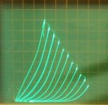
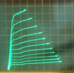
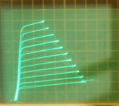
21HB5A/21JZ6 g2 or screen drive curves: (stop that drooling!!)
50 mA/div Vert., 50 V/div Horiz.
I suppose one could combine screen drive with Schade to the driver cathodes if you want to break the tube amp laws. ( super ultra mega linearity)
The RCA handbook has a 50 Watt amplifier (P-P) schematic that uses both the above approach, and the more usual local Schade (R to the output tube grid from plate) approach, combined.
21HB5A/21JZ6 g2 or screen drive curves: (stop that drooling!!)
50 mA/div Vert., 50 V/div Horiz.
I suppose one could combine screen drive with Schade to the driver cathodes if you want to break the tube amp laws. ( super ultra mega linearity)
Attachments
Last edited:
The Data for the 21JZ6 gives max screen voltage as only 220. Can you use it as a triode or UL? Surely only Screen drive or Pentode
Phil
===
I was wondering about this. If I connect the screen (and the beam forming electrodes) to the plate does this limit still apply? I'd like to run it at ~300V for more power if it can be made to work.
Phil
===
I was wondering about this. If I connect the screen (and the beam forming electrodes) to the plate does this limit still apply? I'd like to run it at ~300V for more power if it can be made to work.
I just got a good deal on a lot of 21JZ6 tubes. Spec is attached. I'd like to try triode strapping them. A couple questions come to mind:
Any other ideas would be appreciated. Thanks!
- If I connect the beam forming electrodes to the plate, what does this do to the power rating?
- I've seen some examples where the screen grid is used to drive and G1 is connected to the cathode. Any advantage to this?
1) Connecting the beam formers to the plate defeats the whole purpose for including them in the first place: preventing secondary electrons from increasing the screen current enough to push the screen characteristic into negative resistance. You'd get the same sort of nasty plate current "kinks" that you have with pure tetrodes. Sounds hideous, and makes for instability.
The spec sheet does advise some positive bias on the beam formers to prevent snivets.
2) Screen drive can get you some extra watts at the expense of requiring more driver input swing. You can also take the operation deeper into Class AB and not have the otherwise severe x-over distortions. These days, MOSFET source followers can drive the screens and their heavy current demands, making screen drive more viable than in the "good ol' days". Just be careful if you go this route. Overdrive can result in overheated screens, plate voltages that actually go negative, and the excessive screen currents that can encourage the poofage of driver transistors and finals.
Given that this is a HD final, it probably sounds quite good without needing any assistance from lNFB. If you do need lNFB, there's always parallel ("Schade") feedback, or cathode feedback if your OPT has secondary taps that can accommodate this. For UL, you'd need a source follower that supplies the screen voltage, and feedback voltage from the plates. This can be made adjustable (unlike UL taps) for the best performance. As a side benefit, the high current sourcing capability make for easier to design OPTs.
A PP pair looks like they could do some 60W, much more than you'd ever get trying to use these as triodes.
I was wondering about this. If I connect the screen (and the beam forming electrodes) to the plate does this limit still apply?
Yes.
"I'd like to run it at ~300V for more power if it can be made to work." "triode"
Well, first of all, you don't need high B+ with TV sweep tubes, because they can handle amazing plate currents. Which allows them to use a higher performing, low Z primary, OT.
And I don't know about the 21JZ6s you got, but the 21HB5s were on the $1 list for years. So just use two in parallel for more Watts out if that's an issue. Edcor's got a 1700 Ohm Zpri, 100 Watt, OT that would work for paralleled tubes.
But just for fun:
Looking at the datasheet curves versus screen grid voltages:
at 50V on screen and plate: max g2 current = 4 mA and max Ip = 110 mA
at 150V on screen and plate: max g2 current = 22.5 mA and max Ip = 610 mA
Determine a rough power law for g2 current: (150/50)^1.6 x 4 mA = ~ 22.5 mA
so about 1.6
So at 300V on screen and plate (triode configured): max g2 current = 68 mA and max Ip = 1849 mA,
that would give .068 x 300 = 20.4 Watts on the screen grid.
However, that's MAX Watts using 0V on g1.
For class A operation, average Ip current (and Ig2) would be 1/2 that, so .034 x 300 = 10.2 Watts on g2, exceeding the 3.5 Watt g2 rating.
For class AB operation, we can probably figure 1/2 that again average Ip current though, giving 1/2 the average screen current and Watt dissipation, so 5.1 Watts on g2. Still above the max g2 rating. Class B maybe could cut that by 1/2 again.
Then there is the 220V screen voltage limit, which would be rather exceeded in triode mode at a peak 600 V plate voltage. (I figure you can hit at least 2X the max g2 V safely in triode)
But just for fun (a $1 tube), I put a 21HB5A in triode mode on the curve tracer with 1150V plate peaks, and Da_n if it doesn't still work!! It took -260 V on g1 to cut it off. I'm surprised it didn't develop a g1 to K short at least. I don't think I would recommend this though, this was a cold tube. There's sure to be some inductive spike in class aB, or a hot grid under load, that would flash over.
Last edited:
I've been out a few days and am trying to catch up on all this.
To be clear I was interested in triode strapping mainly just to try it out, and because this tube does not connect the beam plate to the cathode, So I thought that connecting it to the plate might do something "interesting". I guess not.
Running at 300V was again just an idea based on something I read about triode connected tubes being able to handle higher voltages. I appreciate the complete analysis from "smoking-amp". Sounds like it's not a big win.
Can someone point me do a "Dummy's Guide" for Schade feedback. There's a whole lot about it out there, but mostly discussions between folks that already know what it means.
BTW - I paid <2$ a tube, 4 NOS for sure, 5 "test new" according to the seller. I'll get then tonight. I've found that 21V heater compactrons are often a LOT cheaper than the same 6V versions, and you can run them with a cheap-as-dirt 24V transformer and a small dropping resistor, or none if the transformer is wimpy...
The original Schade feedback scheme (the journal paper is on the internet somewhere) used a transformer to series feed an attenuated output signal back to the tube grid (along with the input drive signal) so as to act as negative feedback (by subtraction).
What is typically referred to as Schade NOW, however, is just shunt feedback from plate back to grid using a resistor. This forms a divider network with the preceding driver tube's plate resistor. Much like the two resistor network used to set the gain for an inverting Op. Amp. (the output tube acting as the Op Amp here)
But instead of a voltage applied at the terminal end of the divider resistor, a current is applied at the midpoint between the two resistors. Typically a pentode driver is used to act as the drive signal current source. But some times a triode is used with a degeneration resistor in its cathode circuit to increase its plate resistance. (so looking more like a current source from its plate)
Another alternative is to use high voltage gain in the driver stage, with a follower (typically a HV Mosfet) after that, driving a high value R to act like a signal current source into the output tube grid.
The output tube grid, because of the Neg Fdbk R, looks like a low impedance. (an ideal inverting Op. Amp. would be 0 Ohms there) The feedback R effectively has its AC Ohmic value divided by the output stage gain, much like the Miller effect for plate to grid capacitance in triodes. So this makes for a difficult load to drive, this being the main drawback of shunt Schade operation. (and the output tube grid still needs to get its normal grid voltage swing to operate normally, not being infinite internal gain like the Op Amp.) To drive this low Z node with a current source requires a somewhat heroic V to I converter for the driver stage.
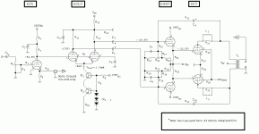
Attached, is an RCA Schade configured amplifier schematic. If you ignore, or remove, the feedback R22, R23 going back to the 6CB6 cathode(s), it would then be a normal Schade configuration. The Schade feedback resistor(s) R21, R24, are from the output tube plates back to the 6CB6 driver tube plates. The 6CB6 load resistors, R15, R19, going to B+ act as an R divider to attenuate the Neg Fdbk, and essentially set the gain of the output tubes. (for an Op. Amp. the V gain would be Rfdbk/Rin or R21/R15) In the tube case it is an Iin to Vout gain that is set. (the Rfdbk determines how much current is fed back, and the Iin has to counter that current and also produce the actual grid swing voltage as well, since the tube is not internally infinite gain like the ideal Op Amp.)
One interesting point about the RCA 50 Watt amplifier is the additional Neg feedback R back to the 6CB6 cathodes. It apparently is used to linearize the V to I conversion in the 6CB6 stage (by shunt current bootstrapping of the cathode R, making it look like a higher value to, in effect, increase the driver plate Rp), as well as to provide additional Neg Fdbk for the output tube.
This circuit looks to be a very practical Schade driver, not requiring any super devices for the driver tube. Apparently it has not been well understood previously in the tube brotherhood. And it certainly could use some simulation testing to verify and illuminate exactly what it is doing and how well.
What is typically referred to as Schade NOW, however, is just shunt feedback from plate back to grid using a resistor. This forms a divider network with the preceding driver tube's plate resistor. Much like the two resistor network used to set the gain for an inverting Op. Amp. (the output tube acting as the Op Amp here)
But instead of a voltage applied at the terminal end of the divider resistor, a current is applied at the midpoint between the two resistors. Typically a pentode driver is used to act as the drive signal current source. But some times a triode is used with a degeneration resistor in its cathode circuit to increase its plate resistance. (so looking more like a current source from its plate)
Another alternative is to use high voltage gain in the driver stage, with a follower (typically a HV Mosfet) after that, driving a high value R to act like a signal current source into the output tube grid.
The output tube grid, because of the Neg Fdbk R, looks like a low impedance. (an ideal inverting Op. Amp. would be 0 Ohms there) The feedback R effectively has its AC Ohmic value divided by the output stage gain, much like the Miller effect for plate to grid capacitance in triodes. So this makes for a difficult load to drive, this being the main drawback of shunt Schade operation. (and the output tube grid still needs to get its normal grid voltage swing to operate normally, not being infinite internal gain like the Op Amp.) To drive this low Z node with a current source requires a somewhat heroic V to I converter for the driver stage.
Attached, is an RCA Schade configured amplifier schematic. If you ignore, or remove, the feedback R22, R23 going back to the 6CB6 cathode(s), it would then be a normal Schade configuration. The Schade feedback resistor(s) R21, R24, are from the output tube plates back to the 6CB6 driver tube plates. The 6CB6 load resistors, R15, R19, going to B+ act as an R divider to attenuate the Neg Fdbk, and essentially set the gain of the output tubes. (for an Op. Amp. the V gain would be Rfdbk/Rin or R21/R15) In the tube case it is an Iin to Vout gain that is set. (the Rfdbk determines how much current is fed back, and the Iin has to counter that current and also produce the actual grid swing voltage as well, since the tube is not internally infinite gain like the ideal Op Amp.)
One interesting point about the RCA 50 Watt amplifier is the additional Neg feedback R back to the 6CB6 cathodes. It apparently is used to linearize the V to I conversion in the 6CB6 stage (by shunt current bootstrapping of the cathode R, making it look like a higher value to, in effect, increase the driver plate Rp), as well as to provide additional Neg Fdbk for the output tube.
This circuit looks to be a very practical Schade driver, not requiring any super devices for the driver tube. Apparently it has not been well understood previously in the tube brotherhood. And it certainly could use some simulation testing to verify and illuminate exactly what it is doing and how well.
Attachments
Last edited:
Can someone point me do a "Dummy's Guide" for Schade feedback. There's a whole lot about it out there, but mostly discussions between folks that already know what it means.
I used this type of lNFB with the Vixen. Schade's paper Beam Power Tubes (scroll down) recommended feeding back 10% of the plate AC. The design nominal power output for the load taken from the STC 807 application white paper was 26.5W, but since this design includes grid drivers, it goes a bit into AB2, and the measured power out at 1000Hz was a little bit over 32W. So use that value:
P= V2/R
V= sqrt(32 * 6600)= 459.57VRMS
V= 459.57 * sqrt(2)= 649.92VP
Vphase= 649.92/2= 324.96VP (325V design nominal)
Vf= 0.1 * 325= 32.5V
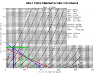
The impedance at the summing node: R12 || R15 || rp
From the loadline for the 6SL7 LTP: rp= 73.8K Therefore:
73.8E3 || 220K || 1M= 52.37K
Given the 10 : 1 voltage division: Rf= 9 * 52.37E3= 471.33K (470K design nominal)
The design nominal input voltage for the grids is 22.5VP/phase, which comes from the LTP. The total voltage is:
22.5 - (-32.5)= 55V
Since the grid resistor is 1M, that means a current of 55uA. However, the LTP is supplying less voltage, making the effective grid resistor
Rg`= 22.5/55E-6= 409K.
This appears in parallel with the plate loads, making the AC loadline:
RP`= 143K (design nominal)
This is the value used for the AC (blue) loadline. It does load down the plates quite a bit, but the h2 estimate still looks pretty good, and will be much less in practice since you're not using very much of the entire output swing. It's less than 1.0%, and since it's mainly h2, you lose that since even order harmonics null in balanced circuits like LTPs.
The estimated gain for this LTP is 25, and the actual measured gain is 25 -- a 0% error! O. Schade's recommend was bang on, as the lNFB really helps clean up all sorts of pentode nastiness when using the 6L6/807 and other 6L6-oids. All that remains is adding enough gNFB to help take the "edge" off. Other pents probably don't need the extra help, such as 6BQ6GAs. These make mainly h3, and all you need is some gNFB.
BTW - I paid <2$ a tube, 4 NOS for sure, 5 "test new" according to the seller. I'll get then tonight. I've found that 21V heater compactrons are often a LOT cheaper than the same 6V versions, and you can run them with a cheap-as-dirt 24V transformer and a small dropping resistor, or none if the transformer is wimpy...
Your odd heater voltages make for some outstanding bargains. I got a bunch of 21LR8s and 36LW6s for future projects. The 21LR8s were dollar bargain specials, and these days you'll have a difficult time even finding 6LW6s, and you'll pay a fortune If you do. These were last generation Octals for color TV sets and are real beasts. As audio finals, you can get north of the century mark for bigwatt amps. Unforch, these tended to attract a lot of attention from hams and operators of illegal CB linears, so not many left. The 36LW6s weren't exactly dollar bin bargains, but still way less than audiophool expensive VTs.
Also got some 12AV5s, and a few 25BQ6GAs, both adaptable to a current design that uses the 6.3V versions of both.
Attachments
- Status
- This old topic is closed. If you want to reopen this topic, contact a moderator using the "Report Post" button.
- Home
- Amplifiers
- Tubes / Valves
- Advice on triode connecting a 'JZ6 tube