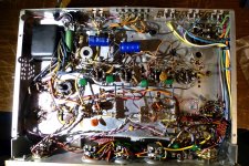
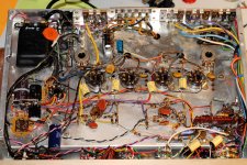
Recently I decided to take a plunge into tubes and purchased a vintage Bogen AP-200. This is an integrated amplifier with 12AX7-based phono stage and phase inverters; the power section uses 4x 7355 tubes and delivers around 25 WPC.
The amp was partially restored by previous owner(s): I was told coupling caps and some resistors were changed. However, electrolytic PS caps are original and I was advised to replace them to get rid of hum. They are C52 (4x 20 mkF/450 V) , C53 (3x 20 mkF/450 V), C54 and C55 (30 mkF/150V each) packed in cans.
I worked on SS amps; however, this is my first tube piece so please pardon my ignorance and stupid questions. How should I change caps that are in cans and what model and manufacturer are preferred? Also, in SS gear people often replace old PS electrolytes with new of higher capacity to get better bass. Can I do it here?
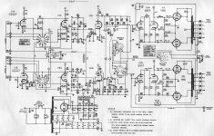
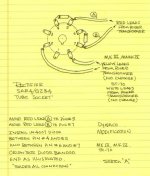
I’ve also read that if a selenium rectifier is used in old amps it should be replaced with a diode and a resistor. Looking on schematics and Bogen itself I didn’t find any; just two old diodes and a new one. Do you think I have a selenium rectifier and should I replace the two old diodes, X1 and X2?
One more thing I’d like to do with the amp is to use it as a preamp or power amp and install “pre out-power in” RCA jacks for this purpose. I think I can do it between Pin 6 of the “mode” selector and the C18/C45 0.01 mkF cap that feeds grids of V3A/V7A (shown by arrowheads at the last picture). The plan is to remove old “Converter output/Third channel” RCA jacks and associated resistors and wiring, install two pairs of new jacks, disconnect Pins 6 of mode selector from C18/C45 then connect it to “pre out” jacks through a new 0.01 mkF/250 V cap. Connection wires will be with screen grounded to “pre out” jacks. The “power in” jack will be connected to C18/C45 with screened wire grounded to “power in” jacks. The C18/C45 cap will be upgraded from ceramics to better type (polystyrene?) 0.01 mkF/100 V.
Do you think it’s the right way of adding pre out-power in jacks here?
In addition I would very much appreciate any and all advises on how to upgrade this amp. I like how its sounds now and I believe it could be greatly improved.
The amp was partially restored by previous owner(s): I was told coupling caps and some resistors were changed. However, electrolytic PS caps are original and I was advised to replace them to get rid of hum. They are C52 (4x 20 mkF/450 V) , C53 (3x 20 mkF/450 V), C54 and C55 (30 mkF/150V each) packed in cans.
I worked on SS amps; however, this is my first tube piece so please pardon my ignorance and stupid questions. How should I change caps that are in cans and what model and manufacturer are preferred? Also, in SS gear people often replace old PS electrolytes with new of higher capacity to get better bass. Can I do it here?
I’ve also read that if a selenium rectifier is used in old amps it should be replaced with a diode and a resistor. Looking on schematics and Bogen itself I didn’t find any; just two old diodes and a new one. Do you think I have a selenium rectifier and should I replace the two old diodes, X1 and X2?
One more thing I’d like to do with the amp is to use it as a preamp or power amp and install “pre out-power in” RCA jacks for this purpose. I think I can do it between Pin 6 of the “mode” selector and the C18/C45 0.01 mkF cap that feeds grids of V3A/V7A (shown by arrowheads at the last picture). The plan is to remove old “Converter output/Third channel” RCA jacks and associated resistors and wiring, install two pairs of new jacks, disconnect Pins 6 of mode selector from C18/C45 then connect it to “pre out” jacks through a new 0.01 mkF/250 V cap. Connection wires will be with screen grounded to “pre out” jacks. The “power in” jack will be connected to C18/C45 with screened wire grounded to “power in” jacks. The C18/C45 cap will be upgraded from ceramics to better type (polystyrene?) 0.01 mkF/100 V.
Do you think it’s the right way of adding pre out-power in jacks here?
In addition I would very much appreciate any and all advises on how to upgrade this amp. I like how its sounds now and I believe it could be greatly improved.
Attachments
You have to be VERY careful about increasing the total (I read 40 μF.) capacitance in the 1st position of the PSU filter. Vacuum rectifiers will arc over and be damaged at turn on, if that capacitance is too large. What is the rectifier tube type? I'm guessing it's a 5U4.
The schematic shows signs of both cheapness and expenditure. Taking O/P tube B+ off the 1st filter position is cheap. OTOH, Bogen did spend on a DC heater supply for the small signal tubes. If a choke of about 1.5 H. and appropriate current rating can be "shoehorned" into the chassis, the filter feeding the O/P tubes can be made CLC, instead of just C, which allows the reservoir position capacitance to rise. A choke isolates the vacuum rectifier from the remainder of the PSU filter.
I don't know if replacement 7355s can be sourced at "reasonable" cost. A quick look at the 7355 data sheet suggests you might be able to rework around EL34 class tubes. Get the opinion of an EXPERT, like Jim McShane.
Replacing all of the SS diodes with Schottkys of appropriate rating is (IMO) a good thing. You definitely get rid of any ticking toxic time bomb selenium and, unlike other SS diodes, switching noise free.
The schematic shows signs of both cheapness and expenditure.
Taking O/P tube B+ off the 1st filter position is cheap. OTOH, Bogen did spend on a DC heater supply for the small signal tubes. If a choke of about 1.5 H. and appropriate current rating can be "shoehorned" into the chassis, the filter feeding the O/P tubes can be made CLC, instead of just C, which allows the reservoir position capacitance to rise. A choke isolates the vacuum rectifier from the remainder of the PSU filter.I don't know if replacement 7355s can be sourced at "reasonable" cost. A quick look at the 7355 data sheet suggests you might be able to rework around EL34 class tubes. Get the opinion of an EXPERT, like Jim McShane.
Replacing all of the SS diodes with Schottkys of appropriate rating is (IMO) a good thing. You definitely get rid of any ticking toxic time bomb selenium and, unlike other SS diodes, switching noise free.
Last edited:
I would replace the top mounted can capacitors. Antique Electronic Supply has a large selection of replacements. Look for the brand "CE Manufacturing" for starters, but you don't "need" to use those. Other options are the dual can capacitors from F&T or JJ/Tesla, and the remaining capacitors needed not in the can itself can be soldered under the chassis. You can also restuff the old cans with small modern electrolytics, but I find this is much harder. Make sure the first cap right after the rectifier is no larger than what is recommended on the rectifier data sheet.
Here's one I did. Blocked off the original filters and put them inside, save for the last one that's under low stress and measured good for value, loss and leakage. If you can't prove it beyond a shadow of a doubt, replace it. Note added fuse and terminals for bias supply parts. In hindsight, I'd use a bit higher fuse.
Attachments
Adding a fuse is absolutely essential! I can't believe the Bogen didn't use one!
The preamp out will have a very high impedance, and may roll off highs due to cable capacitance. For example, look at the cap values in the high filter - 10s of pF. Most cables are around 20 pF per ft.
The preamp out will have a very high impedance, and may roll off highs due to cable capacitance. For example, look at the cap values in the high filter - 10s of pF. Most cables are around 20 pF per ft.
Thank you everyone for good suggestions,
The 40 uF is C52A+C52B, right? So I suppose using of one 40uF cap instead of 2x 20 uF will be OK.
It’s a GZ34; I have a new JJ GZ34S.
The 1.5 H choke unfortunately wouldn’t fit underneath the chassis. Smaller choke of 0.5 H or so might; however, how big will be benefits of installing it?
Regarding tubes, I do have a spare quad of 7355.
Selenium rectifier should look like a little stack of cards, not like a resistor or cap or diode, right? If this is so, there is no such rectifier in the Bogen. The X3 diode is already replaced with IN4007 by previous owner(s). X1 and X2 left; I might replace them with IN4007s. Are they Schottkys?
I am going to install a fuse and also a new socket for the three-prong cord, attaching a green "ground:” wire to the chassis. The reason for this is that the Bogen manual explicitly says: “Ground the unit by attaching a wire from a COM terminal on the chassis rear to a good ground such as the metal frame of the wall outlet or a water or steam pipe”. I might even have a three-prong socket with the fuse holder sitting around. The two power outlets at the rear and the "death cap" C56 will be removed.
Thank you for pointing on this. Actually, I am much more interested in using Bogen as the power amp than as the pre. However, is it any way to lower tube amp output impedance?
By the way, high and low filter switches will be bypassed to improve the quality of sound: fewer switches, especially old, less connections, less signal losses. Very few people use these filters now and I am not one of them.
You have to be VERY careful about increasing the total (I read 40 μF.) capacitance in the 1st position of the PSU filter.
The 40 uF is C52A+C52B, right? So I suppose using of one 40uF cap instead of 2x 20 uF will be OK.
I'm guessing it's a 5U4.
It’s a GZ34; I have a new JJ GZ34S.
… If a choke of about 1.5 H. and appropriate current rating can be "shoehorned" into the chassis, the filter feeding the O/P tubes can be made CLC, instead of just C, which allows the reservoir position capacitance to rise. A choke isolates the vacuum rectifier from the remainder of the PSU filter.
I don't know if replacement 7355s can be sourced at "reasonable" cost…
The 1.5 H choke unfortunately wouldn’t fit underneath the chassis. Smaller choke of 0.5 H or so might; however, how big will be benefits of installing it?
Regarding tubes, I do have a spare quad of 7355.
…Replacing all of the SS diodes with Schottkys of appropriate rating is (IMO) a good thing. You definitely get rid of any ticking toxic time bomb selenium and, unlike other SS diodes, switching noise free.
Selenium rectifier should look like a little stack of cards, not like a resistor or cap or diode, right? If this is so, there is no such rectifier in the Bogen. The X3 diode is already replaced with IN4007 by previous owner(s). X1 and X2 left; I might replace them with IN4007s. Are they Schottkys?
Adding a fuse is absolutely essential! I can't believe the Bogen didn't use one!
I am going to install a fuse and also a new socket for the three-prong cord, attaching a green "ground:” wire to the chassis. The reason for this is that the Bogen manual explicitly says: “Ground the unit by attaching a wire from a COM terminal on the chassis rear to a good ground such as the metal frame of the wall outlet or a water or steam pipe”. I might even have a three-prong socket with the fuse holder sitting around. The two power outlets at the rear and the "death cap" C56 will be removed.
…The preamp out will have a very high impedance, and may roll off highs due to cable capacitance. For example, look at the cap values in the high filter - 10s of pF. Most cables are around 20 pF per ft.
Thank you for pointing on this. Actually, I am much more interested in using Bogen as the power amp than as the pre. However, is it any way to lower tube amp output impedance?
By the way, high and low filter switches will be bypassed to improve the quality of sound: fewer switches, especially old, less connections, less signal losses. Very few people use these filters now and I am not one of them.
It’s a GZ34; I have a new JJ GZ34S.
A GZ34/5AR4 is supposed to be able to take as much as 60 μF. Unfortunately, all of JJ's Octal production is unreliable and highly suspect.
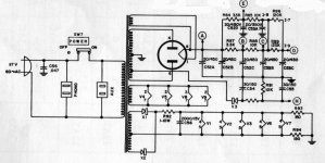
 Definitely install the SS diode tweak, as shown in the uploaded graphic, but use UF4007s, not 1N4007s. I suppose a 47 μF. 1st filter cap. will be OK.
Selenium rectifier should look like a little stack of cards, not like a resistor or cap or diode, right? If this is so, there is no such rectifier in the Bogen. The X3 diode is already replaced with IN4007 by previous owner(s). X1 and X2 left; I might replace them with IN4007s. Are they Schottkys?
The 1N4007 is a very noisy PN junction diode, rated for 1000 PIV. The UF4007 is a drop in replacement for the 1N4007 that's MUCH quieter. Obviously, a 1000 PIV part is overkill in the low voltage heater and bias supplies, but certainly does no harm.
Attachments
Thank you Eli,
After doing this diode tweak, should I completely remove the GZ34 rectifier tube? Alternatively, if JJs rectifier tubes are unreliable, perhaps I need to get one of other brands instead?
After doing this diode tweak, should I completely remove the GZ34 rectifier tube? Alternatively, if JJs rectifier tubes are unreliable, perhaps I need to get one of other brands instead?
A GZ34/5AR4 is supposed to be able to take as much as 60 μF. Unfortunately, all of JJ's Octal production is unreliable and highly suspect.
The 1N4007 is a very noisy PN junction diode, rated for 1000 PIV. The UF4007 is a drop in replacement for the 1N4007 that's MUCH quieter. Obviously, a 1000 PIV part is overkill in the low voltage heater and bias supplies, but certainly does no harm.
The SS diode tweak augments the vacuum rectifier, but does not replace the tube. The "sand" provides some extra PIV headroom. Current production 5AR4s are not all they should be, but the cost of NOS is hideous.  Use the JJ tube, after adding the tweak to its socket. If the JJ product gives you trouble, such as arcing, replace it with a Sovtek.
Use the JJ tube, after adding the tweak to its socket. If the JJ product gives you trouble, such as arcing, replace it with a Sovtek.Can I suggest:
Add an AC fuse, and also fuse both HT secondary winding arms, not the CT, as there may be an issue with bias supply if a CT fuse blows.
1N4007 should be fine for the augment job, because the valve diode will inhibit reverse current flow.
You could decouple the output tube grid bias at the balance adj pot ends, and also add in some protection resistors from wiper to pot ends - unless you're happy to guarantee the pot's performance. A 1 ohm cathode sense for each output valve may make it easier for you to set up the amp.
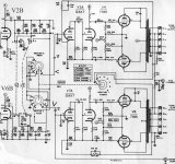
It would be interesting to identify all the schematic errors (eg. R31, 71) and if the output windings are grounded as shown.
Add an AC fuse, and also fuse both HT secondary winding arms, not the CT, as there may be an issue with bias supply if a CT fuse blows.
1N4007 should be fine for the augment job, because the valve diode will inhibit reverse current flow.
You could decouple the output tube grid bias at the balance adj pot ends, and also add in some protection resistors from wiper to pot ends - unless you're happy to guarantee the pot's performance
. A 1 ohm cathode sense for each output valve may make it easier for you to set up the amp.It would be interesting to identify all the schematic errors (eg. R31, 71) and if the output windings are grounded as shown.
Can I suggest:
… fuse both HT secondary winding arms, not the CT, as there may be an issue with bias supply if a CT fuse blows…
I beg your pardon but I don’t understand the tube lingo yet. What is (are) HT and its “secondary winding arms” as well as CT?
…You could decouple the output tube grid bias at the balance adj pot ends, and also add in some protection resistors from wiper to pot ends - unless you're happy to guarantee the pot's performance
This decoupling means a small capacitor such as 0.001 mkF/200 V between contacts of the bias pot and resistors such as R 36 and R38? The “protection resistors from wiper to pot end” should be something like 1 MOhm? Or should I just replace pots with the new multiturn Bournes similar to ones installed in the SS amps but higher voltage (200v)?
…It would be interesting to identify all the schematic errors (eg. R31, 71) and if the output windings are grounded as shown.
The 160 KOhm R31, R30 and their other channel counterparts are there; R 30 is connected to R29 which is 1.2KOhm; however, R29/R68 are bypassed by a small 1.5 nF cap and connected to mode selector rather than grounded.
Measured resistance of output windings to ground: 32 Ohm has 1-0.9 Ohms; 16 has 1.0 ; 8 has 0.8 and 4 has 1.2 Ohm resistance.
Looking at the PS caps replacements, can caps from Antique Electronic Supply are around $32 apiece and I need three while single Nichicons from Mouser are around $1.50. I’ll go with Mouser since most of my audio budget for this amp is already spent on new coupling and signal path caps, signal path resistors and new phase inverter tubes. Phono stage components will also be replaced.
Still thinking about adding a choke as Eli Duttman suggsted. Could I mount it at the top of the amp or for safety reasons high-voltage devices must be mounted underneath where they are not easily accessible? If adding a choke, how can I calculate its current rating?
A 5AR4 is rated for up to 250 mA. You want any filter choke that's added to be at least as capable. A Hammond 159T is quite suitable.
You should find the coils of the magnetics already in place perpendicular to each other. Ideally, the coil of the choke will be perpendicular to everything already there. You are trying to exploit all 3 spatial planes. The fancy name is orthogonal. Such mounting minimizes stray field cross coupling between parts. Practical considerations frequently make ideal mounting not feasible. Should that be the case, mount the choke "diagonally". Avoid coils being parallel to each other.
You should find the coils of the magnetics already in place perpendicular to each other. Ideally, the coil of the choke will be perpendicular to everything already there. You are trying to exploit all 3 spatial planes. The fancy name is orthogonal. Such mounting minimizes stray field cross coupling between parts. Practical considerations frequently make ideal mounting not feasible. Should that be the case, mount the choke "diagonally". Avoid coils being parallel to each other.
Sorry about the abbreviations.
HT= high tension=high voltage. These are the ends of the winding going to the rectifier diodes.
CT=centre tap = the middle tap in the HT winding that goes to ground symbol. A fuse is normally inserted in this lead.
Decoupling is a capacitor that makes the bias supply look like ground at signal frequencies - so a low impedance compared to the 330k, and compared to the 50-100k that the pot may present. So perhaps a little 1uF 50V wima. This is just a pedantic addition that wouldn't be noticeable.
Certainly a multiturn Bournes should be reliable - there is only a lowish voltage at that point. Yup, 1Meg would be fine.
You may also get some benefit from reading up on basic grounding schemes, and even distributed star grounding, and check out how your amp rates with respect to how it would be done nowadays. A couple of simple cable moves can sometimes make a lot of difference to noise and hum.
Last edited:
- Status
- This old topic is closed. If you want to reopen this topic, contact a moderator using the "Report Post" button.
- Home
- Amplifiers
- Tubes / Valves
- Help needed on restoring a Bogen AP-200 amp