Lynn
You stated: "Returning to the previous post about common-mode feedback, an offbeat variant of both circuits is replacing the two fixed Rfb resistors with a single pot (Rfb pot), the Rk resistor with a pot (Rk pot), and then cross-connecting the two wipers with a high-value capacitor (in the 40uF to 100uF range)."
I get the Rfb part but the setup with the Rk pot? I see four versions here:
1. Two ends of the pot attached to the respective cathodes with the wiper to ground and the cap to wiper (ground), or
2. One end to the shared cathodes, the other to ground. The wiper to ground and the cap to wiper (ground), or
3. One end to shared cathodes, the other to ground. The wiper to shared cathodes and the cap to wiper (shared cathodes), or
4. One end to shared cathodes, the other to ground. The wiper to ground and the cap to shared cathodes.
Can you clarify please which version or is there another?
The circuit I posted doesn't work. Although there's common-mode feedback, it's in the wrong phase ... it's positive feedback, which would amplify the common-mode signal, hardly the desired result.
The feedback could be sensed at the following stage, which would give negative common-mode feedback. However, phase and stability issues might arise, since the signal flows through two capacitors before it arrives back at the common cathodes. And it doesn't behave too well when the power tubes draw grid current.
Last edited:
Lynn, Zigzagflux,
I am using a e182CC currently to drive a 300B directly as I just build an adapter to reuse (for experimentation) my EL34 amp which is a clone of http://www.triodedick.com/monobill/monobill schema versterker.GIF ...it works, but is to silent and dimm...as the EL34 in triode had more than double gain.
I can generate with my DHT-Dac (9018 in Dual Mono, 9038 next with LTP running 801A) very high output-levels (OPT LL1692A), this is currently 8Vpp, but I can increase this to 16Vpp or more.
In this constellation: Could I not use a one stage-driver ?
Let's say e182CC at 15mA and 200V at -8 ? Obvisously only transfomer-coupled to get a flat loadline.
The curves above 10mA look pretty good:

Any immediate reactions to that ? Or is the 45/46 driver stage in any case the way to go ?
I really like to vivid style of the e182cc which is very life-like...and typically more stages = more problems as each part is audible.
I am using a e182CC currently to drive a 300B directly as I just build an adapter to reuse (for experimentation) my EL34 amp which is a clone of http://www.triodedick.com/monobill/monobill schema versterker.GIF ...it works, but is to silent and dimm...as the EL34 in triode had more than double gain.
I can generate with my DHT-Dac (9018 in Dual Mono, 9038 next with LTP running 801A) very high output-levels (OPT LL1692A), this is currently 8Vpp, but I can increase this to 16Vpp or more.
In this constellation: Could I not use a one stage-driver ?
Let's say e182CC at 15mA and 200V at -8 ? Obvisously only transfomer-coupled to get a flat loadline.
The curves above 10mA look pretty good:
Any immediate reactions to that ? Or is the 45/46 driver stage in any case the way to go ?
I really like to vivid style of the e182cc which is very life-like...and typically more stages = more problems as each part is audible.
Last edited:
Blitz,
You are certainly welcome to give it a shot, but I gave up on the 7119 and its variants with transformer coupling a long time ago. Cap-coupled they might be great, but with xfmr load I failed to get reasonable high frequency phase matching, and this was when trying to drive the 46 stage. Based on this lack of success, attempting to drive the 300B stage was never a consideration. The interstage transformers were quality units, by different manufacturers, with no luck. Subjective sound quality agreed closely with objective measurements.
I don't know that it's fair to blame the tube or the transformer; the application just isn't optimized at the signal levels, currents, and impedances involved. Perhaps Pieter's latest IT versions perform much better than the other mfg's I have tried, as they are likely better optimized for the source impedance. Perhaps trying out the Monolith bifilar transformer would work; all you can do is try.
It also largely depends on how severe you want to push the 300B stage. If all you want is 2W peak output, a single stage might be fine. But if you end up approaching grid current on the 300B stage, I wish you luck with anything but a highly robust driver stage.
Hmmm....do you have any explanation for that observation ? In theory it has a low rp and can deliver a lot of current...and I believe this was what Lynn used for his first stage...and I believe the 300B needs about 5mA Minimum for a good slew rate at 50000Hz, so running 15 mA should adress this...in theory.
...but I remember that I tried them to work with a LL1668 Anode Choke (amorphous), especially made for this application (PP). And it sounded weird / very warm / not really transparent which was not what I expected, so maybe this mirrows your experience. But I will try this next and prepare in parallel the 45 stage.
By the way: Which Current Source did you use in your 45 Stage ?
Last edited:
I suspect it had a lot to do with parasitics in the transformer, especially at higher frequencies. So in that sense, the transformer is to blame. A Lundahl multilayered winding (1692A IIRC) had the issue, as did the Onetics designed specifically for the purpose. But I believe the rp of the tube was also responsible for the resonance with those parasitics, as the lower the rp the better the frequency extension before the phasing got really messed up.
Don't forget the miller capacitance, either. The higher the gain of the tube, the more miller gets in the way. So you have the miller of the input stage, parasitics of the transformer, followed by grid capacitance of the stage being driven. It really gets messy quick.
And the challenge is not strictly slew rate; it is balance of gain/phase between the pushing device and the pulling device, and the resultant output from the IT. If gain AND phase are not tightly matched, distortion enters in.
I tested those stages and was (years later) able to compare to the bifilar IT by means of a lissajous test on the scope. It is very revealing. No contest, as long as you can tolerate the voltage limitations of the bifilar construction.
Many topologies are not sensitive to this need for gain/phase matching, as it doesn't really exist in SE stages, and the vast majority of PP stages either start as SE or end as SE. You feed a SE signal into a concertina (which is kind of a 'perfect' splitter), serve a PP stage where it gets recombined into SE to the speaker. This particular topology retains the PP throughout each stage, where phasing issues can accumulate. By the time you reach the output transformer, the damage is done.
My current sources are the basic cascode depletion mode FET. If I recall a DN2540 on the bottom and an IXYS 10M45S on top.
Lynn, Zigzagflux,
I am using a e182CC currently to drive a 300B directly as I just build an adapter to reuse (for experimentation) my EL34 amp which is a clone of http://www.triodedick.com/monobill/monobill schema versterker.GIF ...it works, but is to silent and dimm...as the EL34 in triode had more than double gain.
I can generate with my DHT-Dac (9018 in Dual Mono, 9038 next with LTP running 801A) very high output-levels (OPT LL1692A), this is currently 8Vpp, but I can increase this to 16Vpp or more.
In this constellation: Could I not use a one stage-driver ?
Let's say e182CC at 15mA and 200V at -8V ? Obviously only transformer-coupled to get a flat loadline.
The curves above 10mA look pretty good:
View attachment 687360
Any immediate reactions to that ? Or is the 45/46 driver stage in any case the way to go ?
I really like to vivid style of the e182cc which is very life-like...and typically more stages = more problems as each part is audible.
I'd try PP triode-connected 6V6's (or similar) as a first step, and see how you like that. You have plenty of symmetric drive voltage, and you can run the small power tubes (as drivers) in the 20~30 mA current range. If you like that sound, try 45's or 46's at the same operating point and see how that works for you.
Moving on to ZigZagFlux's comments, I think part of the problem is running the input or driver stage with too little current. In both the Amity and Karna amps, I run the 5687/7044/7119 at 22 mA per side, and I get pretty reasonable HF performance, at least by measurement and subjective sonics. When I try the 6SN7 experiment, they'll be running at 10~11 mA per side into the new Tribute/Pieter transformer, and will be compared (with the same transformer) to the existing 5687/7044/7119 setup (running at 22 mA per side). The measurements and sonics should give the answer.
Part of the issue with "too little current" is the challenge of driving the stray capacitance of the transformer in addition to the Miller capacitance of the following stage. This opens the flat load-line into an ellipse, which results in distortion when the ellipse dips into the low-current region. Since the low-current region is phase-shifted 90 degrees by the reactive load, this can fall into the zero-crossing region, the worst possible place for it to be. This would mimic slew-rate distortion, since the HF distortion would be strongly frequency and operating-current dependent.
A direct comparison with a much simpler PP RC-coupled input stage would be worthwhile, with the plate-load resistor in the typical 3~4x Rp range. Compare distortion at 5 and 10 kHz and see what you find.
If memory serves, the distortion signature of most of the tubes Gary Pimm and I tested appeared to be a function of manufacture. Changing the operating current by a factor of 3 only affected the higher harmonics (5th and higher) by 3 dB, and while retaining the overall structure. And this was using a special Gary Pimm instrument that displayed harmonics down to -120 dB.
Last edited:
Making some progress...This is what I tried:
I used the e182cc/7119 before at 5.3mA 150V with a 27K Anode resistor to drive a triode connected EL34 in PP. Setup is a LTP with a CCS in the tail.
I changed this to a 300B by using an adaptor into the EL34 sockets and coleman regs to heat this. This was indended as I want to understand exactly what is doing what and therefore only one step at a time.
The sound became obviously a lot quieter, but as well a lot better detailed and natural. Actually the 300B (or better: this setup) sounded leaner and thinner (at 450V, -102V, 60MA, fixed bias) than the El34...i cannot find the myths about the dull and mid-orientated sound.
Next step: I raised the driver voltage to 440V and set the anode voltage to 210V to get a negative bias of -8.2V. I changed my I/V-resistor in the DAC to give me a double voltage swing as a quick fix to see where we get to.
Voltage swing at the grid of the 300B is now nearly 200Vpp. It is loud enough for sure. How does it sound ? Not so good. Even with 8.3mA now and a fairly flat load line of the 27K resistor it sounds compared to the el34-setup now thin, not very dynamic, stressed.
What would be your bet why it sounds like that ?
Next step: I will lower the voltage of the driver and try a similar setup with an anode choke instead of the resistor, followed by Monilith IT I have here laying around. Let's see if RC is here the issue or if the e182cc in principle is just to wimpy to drive a 300B...in parallel I am already preparing the 45 to come into the game (another set of coleman filaments to be soldered).
Last edited:
Well, I believe I am already at the upper end with the 210V, no ? Nevertheless, this is now playing for a couple of hours and it becomes better and better...maybe I was just not patient enough...The amount of details is incredible. 3D much improved. The One-Stage Driver concept for sure needs more attention.
I am considering to buy a quad of EML 20B...rp of 3k3, mu of 20, 43mA current and DHT...they should give me the same amplification but with a lot more linearity and power. 3k3 would still allow an IT...
I am considering to buy a quad of EML 20B...rp of 3k3, mu of 20, 43mA current and DHT...they should give me the same amplification but with a lot more linearity and power. 3k3 would still allow an IT...
I used the e182cc/7119 before at 5.3mA 150V with a 27K Anode resistor to drive a triode connected EL34 in PP. Setup is a LTP with a CCS in the tail.
I love the 5687 / ECC99 / E182CC / 6N6P family of twin triodes. I've goofed around with them quite a bit, but I've never tried using them to drive a PP IT.
Anyway, I hope I can help a little here.
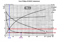
First, what do you define as 'low rp'? With plate voltage of 200V and plate current of 5mA, an E182CC is going to have rp up around 5k ohms -- not way down at 2k or lower. See the attached graphic of E182CC characteristics at 120V plate voltage from the Philips datasheet. With plate voltage = 200V, rp will be higher and gm lower than at 120V for the same plate current (Ip).
It's a common mistake to treat plate resistance as a 'constant.' Only mu is relatively constant at different operating conditions. rp and gm can vary quite a lot, even in very linear triodes.
Generally speaking, if you want to get that 2k ohm rp from a 5687, E182CC/7119, or 6N6P, you need to get the Ip up to 15mA or more, like the >20mA Lynn mentioned. That means lower plate voltage, which means less voltage swing available from the plate. Everything is a compromise.
For 5687 tubes, I like operating points around Vp = 150V, Vg = -4V, Ip = 20mA, Pdiss = 3W (that's near the max).
--
Attachments
Last edited:
Thanks for the heads up...you are absolutely right and I planned to raise the current to 22mA as suggested by Lynn when using an anode choke/IT...the 8.3mA I mentioned are there only because of the 27K of the RC...otherwise I am all in for a much higher current...I used to apply the same bias point you mentioned, but with a 8k2 resistor...with 27k much less distortion, but at the price of less current...which costs you a bit dynamic in the sound.
By the way: The e182cc sounds much, much better than any 6N6p I tried. And I tried many.
By the way: The e182cc sounds much, much better than any 6N6p I tried. And I tried many.
Last edited:
Interested in hearing about your results to come, Blitz. I had tried the 7119 and its variants, as well as the 6n6p. Currents were run at various attempts between 16 and 24 mA, with 22 mA being the sweet spot. There is an old thread here with some of those results; it was a frustrating time for me, as nothing was successful. Most likely I was dealing with strays from the IT, and those strays were not well balanced from the push to the pull side. Hence my final solution of bifilar windings.
It might be very revealing for you to put a scope on each 300B grid as you continue your testing. Check out how the signal looks at each grid as frequency is swept, both in gain as well as phase. Then compare with a differential probe across both grids (which is really what matters, being everything gets summed at the OPT). Of course, if you haven't added the IT yet, I would expect pretty good results up to the point of grid current.
If your goal is a 2-3 W amp, a two stage amplifier is certainly the way to go. If you want to push distortion-free peaks at 10-15W, I will put my bets on the 3-stage build with IT between driver and final.
Keep us posted!
I had 6n6p driving an interstage in PP and enjoyed if for several years but switched to 6e5p triode connected and like it much better. It has a fairly low 1k ohm plate resistance in triode and a quite gm. Sounds very good to me. Had a bit of time finding matched pairs but they are fairly inexpensive.
John
John
Ok, I pulled the trigger on the eml20bv4. Jac/EML gives 5years warrantee, which is quiet nice as well. So, next steps are:
- Testdrive the e182 with anode choke and IT
- Move to eml20b to compare DHT with IDHT with IT.
I was studying EML warranty conditions and came again to the part where they request to use artificial mid-taps (two 33 ohm resistors), even with DC-Heating.
Emission Labs - Introduction
"12. LAST BUT NOT LEAST, THIS ONE. Never use a filament with one end to ground and the other to the the DC module, UNLESS you do not run the tube very hot . This causes the one side of the tube to wear out faster that the other. Here is a drawing that hopefully is self explaining."
The drawing:
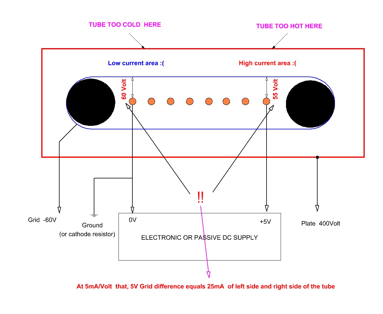
Ok, I get fully the point that for a 300B at 450V -100V this leads to 60mA emission. At -105V, this leads to 39mA and at -95mA this leads to 90mA emssion. So, Jac's picture is right: There is a difference of 30mA between the left and the right side of the plate/filament. So, a hot and a cold side as shown above.
The only thing I do not really get: Why would a mid-tap-setting change that ?The difference of 5V stays, only the ground potential is now between the taps...The hot and cold side remains, no ?
So, if you cant change the hot vs. cold side thing, than a switch would make some sense that yu could switch hot and cold side to consume the tube in a more balanced way, no ?
- Testdrive the e182 with anode choke and IT
- Move to eml20b to compare DHT with IDHT with IT.
I was studying EML warranty conditions and came again to the part where they request to use artificial mid-taps (two 33 ohm resistors), even with DC-Heating.
Emission Labs - Introduction
"12. LAST BUT NOT LEAST, THIS ONE. Never use a filament with one end to ground and the other to the the DC module, UNLESS you do not run the tube very hot . This causes the one side of the tube to wear out faster that the other. Here is a drawing that hopefully is self explaining."
The drawing:
Ok, I get fully the point that for a 300B at 450V -100V this leads to 60mA emission. At -105V, this leads to 39mA and at -95mA this leads to 90mA emssion. So, Jac's picture is right: There is a difference of 30mA between the left and the right side of the plate/filament. So, a hot and a cold side as shown above.
The only thing I do not really get: Why would a mid-tap-setting change that ?The difference of 5V stays, only the ground potential is now between the taps...The hot and cold side remains, no ?
So, if you cant change the hot vs. cold side thing, than a switch would make some sense that yu could switch hot and cold side to consume the tube in a more balanced way, no ?
The only thing I do not really get: Why would a mid-tap-setting change that ?The difference of 5V stays, only the ground potential is now between the taps...The hot and cold side remains, no ?
In fact it doesn't make any difference. Adding resistors + pots is only useful if you use AC heating for hum minimization in stationary conditions (i.e. without signal on the grid). If you have DC supply they only make things worse.
Once manufactures specified if their tubes could be fed with AC only, DC only or both. If EML can't stand DC filament supply it doesn't mean that it is generally true for all tubes.
Anyway I think Rod himself is using the EML 300B and I haven't heard he has had troubles for using his regulators. So you should ask the seller of EML tubes whether he knows for sure about his tubes (i.e. it has been proved with extensive tests). Otherwise he is just putting his hands forward in order to minimise refunds in case of breakage.....IMHO
Anyway it is called thermionic emission for a reason. It's not the voltage from one end to the other respect to ground that controls the emission (or better electron evaporation to form the cloud around the cathode) but temperature which will be uniform all along the filament regardless of DC or AC supply. That picture of unbalanced emission from one side to other is simply wrong, IMHO.
Or better it also depends on what happens next to the emission (i.e. geometry of the tube , field etc....) It might true in some cases but not general. For what I have seen this is a problem for things like electron guns that operate with 50-60 KV accelerating voltage, no control grid and where likely there is no (or very little) cloud around the cathode/filament. In this case I can believe one has hot spot and cold spot using DC heating.
So, if you cant change the hot vs. cold side thing, than a switch would make some sense that yu could switch hot and cold side to consume the tube in a more balanced way, no ?
Hot and cold are referred to the plate. Tube life is 99% dependent of the filament life. I don't think you can change tube life by doing that.
The picture you posted with hot and cold spots is too simplistic, IMHO, because it depends on the real field the electrons will see which is not simply proportional to voltage differential....Therefore the first and very practical assessment is: if you can't see a red plate then it is fine. Performance wise you just go for the better routing....
As I said in the previous post the filament is fine, there is nothing you need to add once you decide to go for the DC (current and voltage) regulated supply because the electron emission depends on its temperature which is rather uniform regardless of AC and DC supply. The filament supply then has the only task of supporting the emission by filling the gaps and preventing electrons going back into the the filament from the cloud.
45, I do not want to hijack zigzagflux's thread, but if he allows this discussion: I follow your logic that the cathode temperature is highly likely to be the same across the cathode. Nevertheless the negative voltage between the grid and voltage defines, how many electrons are allowed to pass to the anode, no ? The more negative this voltage difference is, the more electrons are pushed back and cant pass the grid in their way to the anode. So, Jac's picture is right.
HOT and COLD are here meant more like making a comparison for higher or lower current flow in my opinion and not as a temperature thing. The real point is: If for instance the data sheet says: max Cathode current: 70mA (for a 300B as an example) AND you use this in fixed bias (as I do with Rod's bias regs) with 450V and DC heating (with Rod's filament regs), I should not go above 55mA as 30mA is the max difference, so probably one side will have 40ma emission and the other 70mA.
Well...not sure which case the fixed bias case means in the data shet as there is a second case which is defined as max current for manually adjusted grid bias ...(which is fixed bias, no?) and there the max. is 100mA.
Anyway, I believe Jac makes here the point for the case of not driving the tube towards max power dissipation I guess, so with 450V and 60mA, we are still with 27 Watt at 67,5% of the allowed 40 Watt in a safe area I guess.
I simply did not get his point that the two resistors would change the situation...maybe I give him a call.
Last edited:
Nevertheless the negative voltage between the grid and voltage defines, how many electrons are allowed to pass to the anode, no ? ]
No. It is the actual electric field that accelerates the electrons which is very likely not just proportional to the applied voltage differential.
Of course if one has a filament supply of just 1.5-2V instead of 4-5 and low mu triode it is a better choice! I am plyaing with the type 49 these days. This tube can only work with 2V DC filament supply with typical bias around -20V to -25V. Very linear device.
Anyway, I believe Jac makes here the point for the case of not driving the tube towards max power dissipation I guess, so with 450V and 60mA, we are still with 27 Watt at 67,5% of the allowed 40 Watt in a safe area I guess.
I can understand that. They simply don't have data to fix true maximum limits for their tubes as it was possible in the tubes golden era...
A few years back it was the same with positive grid drive. They could not say anything and for that reason I never bought their type 45.
I do not want to hijack zigzagflux's thread, but if he allows this discussion:
You don't need my permission; deviations are good for any discussion, although hopefully we don't stray too far into capacitor flavors and wire insulation color. I am unashamedly a pragmatist.
Pursue your heating preferences as you see fit; when you get some measurements of the IT performance, bless us with some results
")
- Status
- This old topic is closed. If you want to reopen this topic, contact a moderator using the "Report Post" button.
- Home
- Amplifiers
- Tubes / Valves
- Two driver options for 300B push pull