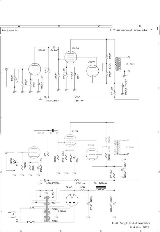
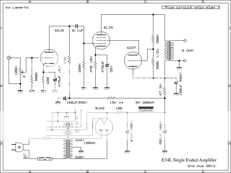
I'm building this diy EL34 amplifier. I can only hear very soft volume even the volume is at max. I can't get any good reading on the EL34 cathode voltage. Even anode plate to ground reading seems funny value. Is this circuit diagram correct. Please help and thanks.
Last edited:
I will check the wiring again. Thanks for reply.That circuit may do strange things on positive signal peaks due to the triode feeding the EL34 screen grid. The main effect will second-order distortion, not low volume. You probably have a wiring error.
Yes I did.Did you connect g3 (Pin1) to cathode (Pin8) of EL34?
I may confused by the upside down drawing. That mean the EL34 g2 connected to the cathode not the anode. Am I right? I measured the 6DJ8 pin 3 and 8 to ground. I'm getting 5.8V.And EL34 g2 goes to the cathode of the triode? The upside-down triode drawing might cause confusion.
Some DC voltage readings might help.
Your smoothing caps are in danger: 700v across a 400V cap will not last long. You may be in danger if you are near them when they blow.
You probably have the wrong transformer, or wired it wrongly. Please take a step back and carefully check all your components and all your wiring before applying power again. What is your local mains supply voltage? How have you wired the transformer primary? Make and use a lamp limiter too.
You probably have the wrong transformer, or wired it wrongly. Please take a step back and carefully check all your components and all your wiring before applying power again. What is your local mains supply voltage? How have you wired the transformer primary? Make and use a lamp limiter too.
The supply voltage to the transformer is 230V. The output is 280V supplied to pin 4 & 6 centre tapped and each side is about 290V. Both sides reported at 590V. From the rectifier pin 8 I measured to ground and getting high at 707V. Where could be wrong? Since EL34 cathode voltage at around 41V but measured with a ammeter I'm getting 44.7mA.Your smoothing caps are in danger: 700v across a 400V cap will not last long. You may be in danger if you are near them when they blow.
You probably have the wrong transformer, or wired it wrongly. Please take a step back and carefully check all your components and all your wiring before applying power again. What is your local mains supply voltage? How have you wired the transformer primary? Make and use a lamp limiter too.
Last edited:
The supply voltage to the transformer is 230V. The output is 280V supplied to pin 4 & 6 centre tapped and each side is about 290V. Both sides reported at 590V. From the rectifier pin 8 I measured to ground and getting high at 707V. Where could be wrong? Since EL34 cathode voltage at around 41V but measured with a ammeter I'm getting 44.7mA.
WOW I have a power transformer with 330v-0-330v output connected to a tube rectifier 5Z3P on pin 8 I'm getting 350v out but when I just connect up the transformer and measure the AC out secondary mine also comes out to 770vac I say there is a miss with your power transformer.
I'm getting some voltages here. From the rectifier 5U4G pin 8 is 707V. EL34 cathode voltage is 41.6V. EL34 Pin 3 is 687V. All the voltages are high.
This isn't possible. If your PTX is truly a 640VCT, then:
VP= 320 * sqrt(2)= 452.55VDC
That's with a C-input ripple filter and no load, even with a vacuum diode like the 5U4GB, where the Vf will drop off to next to nothing when there is no current. If you're getting 707VDC, then either your PTX has a 1000VCT secondary or it has multiple primary taps, and you've connected them wrong. In this case, your PTX is in danger of poofing due to core saturation from excessive volts/turns. If it isn't a multi-tap primary, then you need to call your service provider and report an over voltage situation.
It does happen, and once I was doing a repair job on a clothes dryer where the customer was complaining about poofed heating elements. Checking his AC mains showed he was getting 180V when it should have been 120V. No wonder he was having problems, and I was surprised he wasn't having many more problems and/or hadn't had an electrical fire.
You need to get this sorted out.
I also don't like the design itself. Deriving UL voltages from a cathode follower like this one does is perfectly fine. Not having a cathode load for the UL tube isn't a good practice. We can discuss that later, after you have this over voltage problem fixed.
It is fine when done properly, but here it is not done properly. When the signal swings the output anode above the supply rail the CF stops working as its anode is lower in voltage than its cathode so all g2 sees is whatever triode grid current can flow.Miles Prower said:Deriving UL voltages from a cathode follower like this one does is perfectly fine.
This isn't possible. If your PTX is truly a 640VCT, then:
VP= 320 * sqrt(2)= 452.55VDC
That's with a C-input ripple filter and no load, even with a vacuum diode like the 5U4GB, where the Vf will drop off to next to nothing when there is no current. If you're getting 707VDC, then either your PTX has a 1000VCT secondary or it has multiple primary taps, and you've connected them wrong. In this case, your PTX is in danger of poofing due to core saturation from excessive volts/turns. If it isn't a multi-tap primary, then you need to call your service provider and report an over voltage situation.
It does happen, and once I was doing a repair job on a clothes dryer where the customer was complaining about poofed heating elements. Checking his AC mains showed he was getting 180V when it should have been 120V. No wonder he was having problems, and I was surprised he wasn't having many more problems and/or hadn't had an electrical fire.
You need to get this sorted out.
I also don't like the design itself. Deriving UL voltages from a cathode follower like this one does is perfectly fine. Not having a cathode load for the UL tube isn't a good practice. We can discuss that later, after you have this over voltage problem fixed.
I have sorted the error. It was the faulty transformer. Replaced with a good ones and problem solved. Thanks for all the replies here.
- Status
- This old topic is closed. If you want to reopen this topic, contact a moderator using the "Report Post" button.
- Home
- Amplifiers
- Tubes / Valves
- Need expert help on EL34 SE tube amplifier.